Author Archives: bassemtodary

God of War III’s graphics engine and various implementation

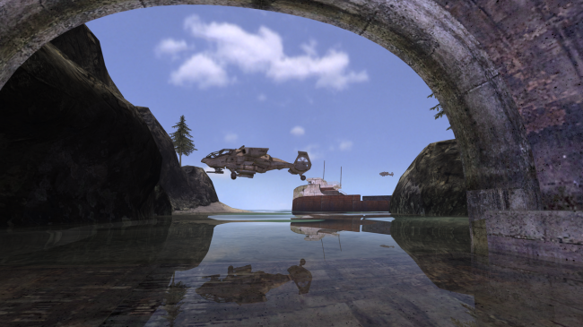
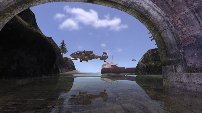
I’ve been playing a lot of God of War III lately and thanks to my Intermediate Computer graphics course, I couldn’t help but consider all the shaders being used. In God of War III, details  in terms of texturing and geometry is not just another step in graphics rendering, but one giant leap for the industry in terms of technology.

Image

Programmable pixel shaders add textures and effects that give a whole new dimension to the quality of the final work. It’s a true generational leap, and performance of the new game, in terms of frame-rate, is in the same ballpark as the previous two God of War titles.

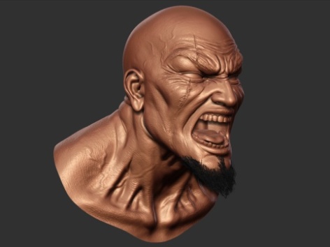
In terms of the character creations themselves, concept art and a low-poly mesh from Maya is handed off to the 3D modellers, who create the basic models using a sculpting tool known as Z-Brush. These models are then given detail – painted in via Photoshop – before being passed along the next stages in the art pipeline to the character riggers and animators.

Image

Kratos himself is a very detailed model, it’s interesting to note that the raw polygon count is considerably lower than the 35,000 or so that comprise the in-game model of Drake in Uncharted 2. But it is significantly higher than Kratos on the PS2 when he had only 5,000 polygons. He had about three textures on the PlayStation 2 and I think he has at least 20 textures on him now. The animation data on him is probably about six times as big.

Image

Kratos is a big guy but did you know that given the intricacy of his model, it would take two Playstation 2’s to fit his memory? That’s not even counting all his weapons that he has to alternate between, eat your heart out Link.

Image

Each character gets a normal, diffuse, specular, gloss (power map), ambient occlusion, and skin shader map. Layered textures were used to create more tiling, and use environment maps where needed.

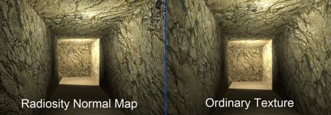
A new technique known as blended normal mapping adds to the realism of the basic model and hugely enhances the range of animation available. Muscles move convincingly, facial animations convey the hatred and rage of Kratos in a way we’ve never seen before.

The system operates to such a level of realism that wrinkles in the character’s skin are added and taken away as joints within the face of the model are manipulated. The musculature simulation is so accurate that veins literally pop into view on Kratos’s arms as he moves them around.

In terms of character movements, over and above the pre-defined animations created by the team, the God of War technical artists also created secondary animation code. Why hand-animate hair, or a serpent’s tail, when the PS3 itself can mathematically calculate the way it should look? The system’s called Dynamic Simulation; and its effects are subtle but remarkable, accurately generating motion that previously took the animators long man-hours to replicate.

From God of War II to God of War III they’ve used Dynamic Simulation more and more to do more secondary animations on the characters. Before, in previous games, the hair or the cloth would be stiff, it would be modelled into the creatures, but now they actually adding motion to those pieces so you will see hair and cloth moving.”

“Towards the end of the previous game, in collaboration with Jason Minters, I created this dynamic system that uses the Maya hair system to drive a series of joints,” adds technical artist Gary Cavanaugh. “Each of the snakes on the gorgon’s head is independently moving. The animator did not have to individually pose all of these animations but they do have control over the physics… it improves a lot of the workflow for animators.”

The tech art team bridges the gap between artists and coders. The ‘zipper tech’ tool on the left shows how they create animated wounds with belching guts, while the shot on the right shows a bespoke animation rig for the gorgon’s tail.

One of the most crucial elements of the cinematic look of God of War III is derived from the accomplished camerawork. Similar to previous God of War epics – and in contrast to Uncharted 2 – the player actually has very little control over the in-game viewpoint. Instead, Sony Santa Monica has a small team whose job it is to direct the action, similar to a movie’s Director of Photography.

Think about it: so long as the gameplay works, and works well, having scripted camera events ensures that the player gets the most out of the hugely intricate and beautifully designed art that the God of War team has put together. When running from point A to point B, why focus the camera on a piece of ground and wall when instead it can pan back to reveal a beautiful, epic background vista?

Perhaps most astonishingly of all, the final God of War III executable file that sits on that mammoth Blu-ray is just 5.3MB in size – uncompressed, and including SPU binaries – in a project that swallows up a mammoth 35GB of Blu-ray space (40.2GB for the European version with its support for multiple languages).

Another core part of God of War III‘s cinematic look and feel comes from the basic setup of the framebuffer, and the implementation of HDR lighting. Two framebuffer possibilities for HDR on the PlayStation 3 include LogLUV (aka NAO32, used in Uncharted and Heavenly Sword), and RGBM: an alternative setup that has found a home in Uncharted 2 and indeed in God of War III.

The basic technical setups for both formats are covered elsewhere but in terms of the final effect and what it means for the look of the game, the result is a massively expanded colour palette which gifts the artists with a higher-precision range of colours in which to create a unique, stylised and film-like look.

Opting for the RGBM setup over LogLUV means a significant saving in processing, although some precision is lost. The degree of that loss isn’t exactly apparent to the human eye, and we can assume it becomes even less of an issue bearing in mind that the final image is transmitted to your display downscaled over the 24-bit RGB link in the HDMI port.

Image

The filmic look of God of War III is boosted via effective motion blur. The shots demonstrate the camera and per-object implementations in the game.

In terms of post-processing effects, the game is given an additional boost in realism thanks to an impressive implementation of motion blur. Superficially, it’s a similar system to that seen in previous technological showcases like Uncharted 2: Among Thieves and Killzone 2, and helps to smooth some of the judder caused by a frame-rate that can vary between anything from 30 frames per second to 60.

Most games that implement motion blur do so just on a “camera” basis – that is, the whole scene is processed – an effect that of variable effectiveness in terms of achieving a realistic look.

According to Sony Santa Monica’s Ken Feldman, motion blur is calculated not just on the camera, but on an individual object and inner object basis too.

God of War’s camera and object motion blur is a subtle but effective contribution to the cinematic look of the game. Here at 30 per cent speed, the effect is more easily open to analysis. Hit the full-screen button for HD, or click on the EGTV link for a larger window.

The basics of the motion blur system effectively mimic what we see on the cinema screen. Movies run at only 24 frames per second, but make it look like it’s smoother. While filming, the shutter of the camera stays open for around 0.04 seconds. During that window of time, movement in the captured image is blurred. It’s that phenomenon that the tech seeks to mimic in God of War III: more cinematic, more realistic.

Initially the game used the RSX chip to carry out a traditional 2x multisampling anti-aliasing effect. This, combined with the game’s lack of high-contrast edges, produced an extremely clean look in last year’s E3 demo. For the final game, the Sony Santa Monica team implemented a solution that goes way beyond that.

MLAA-style edge-smoothing looks absolutely sensational in still shots but the effect often deteriorates with pixel-popping artifacts. In God of War III this only became especially obvious in the scene shown in the bottom right image.

According to director of technology Tim Moss, God of War III worked with the Sony technology group in the UK to produce an edge-smoothing technique for the game that the developers call MLAA, or morphological anti-aliasing. Indeed, Moss’s colleague Christer Ericson took us to task on the specifics of MLAA a few months back in this DF blog post, revealing that the team has put extensive research into this in search of their own solution.

“The core implementation of the anti-aliasing was written by some great SCEE guys in the UK, but came very late in our development cycle making the integration a daunting task,” adds senior staff programmer Ben Diamand.

The specifics of the implementation are still unknown at this time (though Ken Feldman suggests it “goes beyond” the papers Ericson spoke about in the DF piece) but the bottom line is that the final result in God of War III is simply phenomenal: aliasing is all but eliminated and the sub-pixel jitter typically associated with this technique has been massively reduced compared to other implementations we’ve seen. The implementation of MLAA culminates beautifully when it comes to eradicating edge-aliasing within the game.

The custom anti-aliasing solution is also another example of how PlayStation 3 developers are using the Cell CPU as a parallel graphics chip working in tandem with the RSX. The basic theory is all about moving tasks typically performed by the graphics chip over the Cell. Post-processing effects in particular work well being ported across.

The more flexible nature of the CPU means that while such tasks can be more computationally expensive, you are left with a higher-quality result. The increased latency incurred can be reduced by parallelising across multiple SPUs.

In the case of God of War III, frames take between 16ms and 30ms to render. The original 2x multisampling AA solution took a big chunk of rendering time, at 5ms. Now, the MLAA algorithm takes 20ms of CPU time. But it’s running across five SPUs, meaning that overall latency is a mere 4ms. So the final result is actually faster, and that previous 5ms of GPU time can be repurposed for other tasks.

While the detail that the Sony Santa Monica team has put into the characters and environments is clearly immense, it’s the combination with the pure rendering tech that gives the game its state-of-the-art look and feel. The new God of War engine thrives in its handling of dynamic light sources, for example.

God of War III triumphs in handling dynamic lighting, with up to 50 lights per game object. Helios’ head (bottom right) is the most obvious example of the player directly interfacing with dynamic lighting. Dynamic lighting is one of the big features of the game’s engine. It manages to support up to 50 dynamic lights per game object. They are not using a deferred lighting scheme. Our lead programmer What the team did was place lights in Maya and have them update in real-time in the game on the PS3, it’s like being able to paint with lights.

Where there is light, there is a shadow. Or at least there should be. On the majority of videogames, shadowing tech is fairly basic. Producing realistic shadows is computationally expensive, hence we get a range of ugly artifacts as a result: serrated edges that look ugly up close, or cascade shadow maps that transition in quality in stages right before your eyes.

Image

God of War III stands out in this regard simply because you don’t tend to notice the shadows. They’re realistic. The human eye is drawn to elements that stick out like a sore thumb, and that includes shadows. State-of-the-art techniques result in a very natural look. The result is subtle and it works beautifully, thus creating visual feast for players to enjoy as they play a game with graphics that even surpass blockbuster movies.

Global Illumination techniques

The importance of generating realistic images from electronically stored scenes has significantly inreased during the last few years. For this reason a number of methods have been introduced to simulate various effects which increase the realism of computer generated images. Among these effects are specular reflection and refraction, diffuse interreflection, spectral effects, and various others. They are mostly due to the interaction of light with the surfaces of various objects, and are in general very costly to simulate.
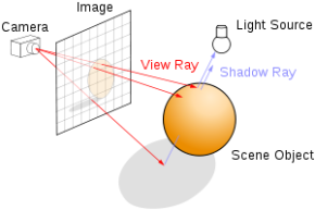
The two most popular methods for calculating realistic images are radiosity and ray tracing. The difference in the simulation is the starting point: Ray tracing follows all rays from the eye of the viewer back to the light sources. Radiosity simulates the diffuse propagation of light starting at the light sources.

The raytracing method is very good at simulating specular reflections and transparency, since the rays that are traced through the scenes can be easily bounced at mirrors and refracted by transparent objects. The following scenes were generated with ray tracers developed at our institute.

Image

Calculating the overall light propagation within a scene, for short global illumination is a very difficult problem. With a standard ray tracing algorithm, this is a very time consuming task, since a huge number of rays have to be shot. For this reason, the radiosity method was invented. The main idea of the method is to store illumination values on the surfaces of the objects, as the light is propagated starting at the light sources.

Deterministic radiosity algorithms, which have been used for radiosity for quite some time, are too slow for calculating global illumination for very complex scenes. For this reason, stochastic methods were invented, that simulate the photon propagation using a Monte Carlo type algorithm.

At our institute we improved the speed of this type of stochastic method by introducing a new algorithm called Stochastic Ray Method. Using the same amount of CPU time, our new algorithm (right image) performs visibly better than the standard Monte Carlo radiosity (left image).

Image

The term raytracing just means that the renderer calculates the path of a ray of light. This can be used in several ways: to calculate an accurate sharp shadow from a light source or to calculate accurate reflections and refractions as light bounces off or passes through an object.

Image

Blender itself uses both the above methods. When people refer to “raytracing” they normally just mean these two things: in other words it generally doesn’t have anything to do with soft shadows.

They follow rays of light from a point source, can account for reflection and transmission. Even if a point is visible, it will not be lit unless we can see a light source from that point. Ray tracing particularly suits perfectly reflecting and transmitting surfaces. Must follow the cast ray from surface to surface until it hits a light source or goes to infinity. The process is recursive and account for absorption. Light from source is partially absorbed and contributes towards the diffuse reflection. The rest is transmitted ray + the reflected ray. From the perspective of the cast ray, if a light source is visible at a point of intersection, we must

1. Calculate contribution of the light source at the point

2. Cast a ray in the direction of perfect reflection

3. Cast a ray in the direction of the transmitted ray

Theoretically the scattering at each point of intersection generates an infinite number of new rays that should be traced. In practice, we only trace the transmitted and reflected rays but use the Phong model to compute shade at point of intersection. Radiosity works best for perfectly diffused surfaces.

Image

The term radiosity is often used to refer to any algorithmn which tries to calculate the way diffuse light bounces off surfaces and illuminates other surfaces: for example light coming through a window, bouncing off the walls in the room and illuminating the reverse side of an object. “Global illumination” or (GI) is probably a better term, since “radiosity” is a specific algorithmn. Ambient Occlusion could be thought of as a type of GI.

Radiosity solves the rendering equation for perfectly diffuse surfaces. Consider objects to be broken up into flat patches (which may correspond to the polygons in the model). Assume that patches are perfectly diffuse reflectors

• Radiosity = flux = energy/unit area/ unit time, leaving patch (watts per square metre)

So, basically, raytracing is for reflections, refraction and sharp accurate shadows, radiosity is for diffuse light bouncing off objects.

Global lighting can be determined through the rendering equation, rendering equation cannot be solved in general so numerical methods are often used to approximate solution. They perfectly specular and perfectly diffuse surfaces simplify the rendering equation. Ray tracing is suitable when the surfaces are perfectly specular. Radiosity approach is suitable when the surfaces are perfectly diffuse. Unfortunately both methods are expensive and massively memory consuming if you trying to implement them for your game.

Shaders, the 3D photoshop Part 2

In my previous blogpost, I went over the many algorithms used in both 2D and 3D computer graphics. I talked about how they are essentially the same. We’ll use a screen shot from my game Under the Radar that I editted in photoshop, before and after respectively.

Image

Image

Drop shadowing in photoshop is the same as shadow mapping in which it checks if a point is visible from the light or not. If a point is visible from the light then it’s obviously not in shadow, otherwise it is. The basic shadow mapping algorithm can be described as short as this:

– Render the scene from the lights view and store the depths as shadow map

– Render the scene from the camera and compare the depths, if the current fragments depth is greater than the shadow depth then the fragment is in shadow

In some instances, drop shadows are used to make objects stand out of the background with a an outline, in shaders this is done with sobel edge filters.

The Sobel operator performs a 2-D spatial gradient measurement on an image and so emphasizes regions of high spatial frequency that correspond to edges. Typically it is used to find the approximate absolute gradient magnitude at each point in an input grayscale image.

In theory at least, the operator consists of a pair of 3×3 convolution kernels. One kernel is simply the other rotated by 90°. This is very similar to the Roberts Cross operator.

These kernels are designed to respond maximally to edges running vertically and horizontally relative to the pixel grid, one kernel for each of the two perpendicular orientations. The kernels can be applied separately to the input image, to produce separate measurements of the gradient component in each orientation (call these Gx and Gy). These can then be combined together to find the absolute magnitude of the gradient at each point and the orientation of that gradient.

In photoshop, filters are added to images to randomize the noise and alter the look. The equivalent in shaders is known as normal mapping. Normal maps are images that store the direction of normals directly in the RGB values of the image. They are much more accurate, as rather than only simulating the pixel being away from the face along a line, they can simulate that pixel being moved at any direction, in an arbitrary way. The drawbacks to normal maps are that unlike bump maps, which can easily be painted by hand, normal maps usually have to be generated in some way, often from higher resolution geometry than the geometry you’re applying the map to.

Normal maps in Blender store a normal as follows:

  • Red maps from (0-255) to X (-1.0 – 1.0)
  • Green maps from (0-255) to Y (-1.0 – 1.0)
  • Blue maps from (0-255) to Z (0.0 – 1.0)

Since normals all point towards a viewer, negative Z-values are not stored, also map blue colors (128-255) to (0.0 – 1.0). The latter convention is used in “Doom 3” as an example.

Those are a majority of effects that shaders use that are similar to photoshop effects, there’s also color adjustment which can be done in color to HSL shaders along with other sorts of effects.

Shaders, the 3D photoshop

The simplest way to describe shaders is that it is the photoshop of 3D graphics; both of them are used to create effects enhancing lighting and mapping, to make the images more vivid and lively, and to give bad photographers, artists and modelers a chance to redeem their miserable work.

Perhaps the greatest thing they have in common are the algorithms used to execute their operations, they’re not just similar, they’re the exact same math operations.

Image

Their primary difference is photoshop is used to manipulate 2D images and shaders alter 3D images, however both images are made up of pixels.

Image

First, the image must be processed, but how? We must define a generic method to filter the image.

Image

As you can see, all elements in the kernel MUST equal 1. We must normalize by dividing all the elements by the sum in the same way we normalize a vector.

The central element of the pixel, which in the case of what we have above is 6, will be placed all over the source pixel which will then be replaced with a weighted sum of itself and pixels nearby.

That’s how it works it works for images normally, but what about in shaders?

Normally we do forward rendering. Forward rendering is a method of rendering which has been in use since the early beginning of polygon-based 3d rendering. The scene is drawn in several passes, then the cull scene becomes renderable against frustum, then the culled Renderable is drawn with the base lighting component (ambient, light probes, etc…).

Image

The problem with shaders is that fragment/pixel shaders output a single color at a time. It does not have access to its neighbours, therefore convolution is not possible.

The first pass is stored in the Frame Buffer Object (i.e. all color is in a texture) and we can sample any pixel value in a texture!

Digital images are created in order to be displayed on our computer monitors. Due to the limits human vision, these monitors support up to 16.7 million colors which translates to 24bits. Thus, it’s logical to store numeric images to match the color range of the display. By example, famous file formats like bmp or jpeg traditionally use 16, 24 or 32 bits for each pixel.

Image

Each pixel is composed of 3 primary colours; red, green and blue. So if a pixel is stored as 24 bits, each component value ranges from 0 to 255. This is sufficient in most cases but this image can only represent a 256:1 contrast ratio whereas a natural scene exposed in sunlight can expose a contrast of 50,000:1. Most computer monitors have a specified contrast ratio between 500:1 and 1000:1.

High Dynamic Range (HDR) involves the use of a wider dynamic range than usual. That means that every pixel represents a larger contrast and a larger dynamic range. Usual range is called Low Dynamic Range (LDR).

Image

HDR is typically employed in two applications; imaging and rendering. High Dynamic Range Imaging is used by photographers or by movie maker. It’s focused on static images where you can have full control and unlimited processing time. High Dynamic Range Rendering focuses on real-time applications like video games or simulations.

Image

Since this is getting quite long, I’ll have to explain the rest in another blog. So stay tuned for part two where we will go over some of the effects of photoshop and shaders and how they’re the same as well as the algorithms behind them.

Full screen effects and their applications in games

A full screen effect is a way in which computer graphics applications can have different special effects added to a scene. Rather than actually rendering a scene with these effects applied to the objects and geometry within it, they are essentially applied after the render. Which means the graphics program creates an image that the user sees, and then applies an effect over this in a way that is seamless. A full screen effect can be used to accomplish numerous tasks, including the addition of motion blur, bloom lighting, and color filtering.Image

To understand how computer graphics can use a full screen effect, it is often the easiest method to first realize how a scene appears. Programs that use Computer Generated Imagery, video games in particular, often render scenes to a display in real time. This means that as a player navigates through a virtual environment, the various objects in a scene that have been created by the developers of that game appear in relation to the player’s position. When the player walks into a room with a box, the game renders the walls, floor and ceiling, and the box in the room as a series of frames or images about 30 times every second.

Image

A full screen effect can then be added to these individually rendered images to create various results. Motion blur, for example, is a phenomenon that can be seen in the real world or on film; objects often appear distorted and blurry as someone moves quickly past them. While this effect can be applied to objects in a virtual scene, it is often easier and less resource-intensive for it to be done as a full screen effect. Multiple partial renders of the objects in a game are created and overlapped so that a blurred image appears to be moving very fast.

Image

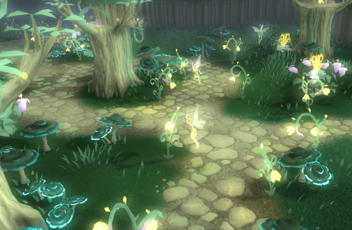
Bloom lighting makes lights in a game appear heavier, to make them stand out, to make a game appear more realistic, give shiny textures of light to bright objects or to provide the graphics with a stylized aesthetic. When different light sources are rendered, the game engine then creates additional renders of increased intensity for the lights and then proceeds to overlap them. A player in a game can then see these lights as being brighter, with a stronger glow. A good example of this effect in use would be Runescape:

Image

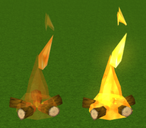
There is also such thing as simulated bloom effects, these are instances where particles are utilized to simulate bloom lighting around certain points of light, the developers do this by registering the particle count output.

Again from Runescape, on the left is how the fire already is, on the right is what a simulated bloom lighting effect would be like:

Image

Color filtering is similarly done. If a game developer wants someone to see a room in black and white part of the time, without having to create multiple textures for objects within it, then this can be achieved through a full screen effect. While the actual textures in a scene are rendered properly, a filtered layer is placed over each frame to change the colors of objects for a player.

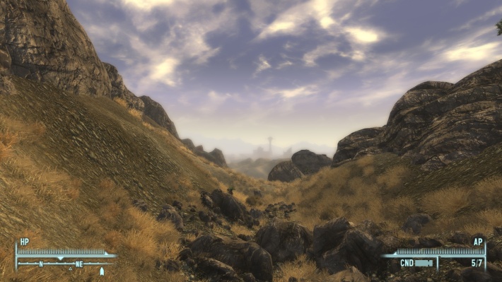
    Depth blur recreates the effect caused by the optics of a lens. Images formed through a lens are in correct focus only when the subject is directly at a certain distance (the focal plane). Objects nearer or farther blur.Notice in this picture how the landscape in the distance is blurred, just like how we would see it in real life:

Image

Often recreated in games by blurring the frame buffer to a temporary texture, and drawing over the frame buffer with that blurred version, alpha blending based on the depth of the scene.

At the end of the day, full screen effects is a fantastic way to either make your games more stylized or realistic.

The usage of toon shading and shadow mapping in computer graphics

Toon shading is a shading method used to make video games look cartoony in order to emulate traditional cartoon animation style, many of which are licensed adaptations of cartoons and anime. If you’re familiar with Dragonball Z or Naruto Shippuden games, you’re most likely aware of what they are, but how are they implemented?

The way toon shading works is that the intensity of the light is being calculated, quantized and used as a basis for a coarse-grained pseudocolor. Accompanying the added intensity is an edge enhancement in which certain areas where the normal are very perpendicular to the eye vector are colored in black and the image will have a noticeable outline similar to a cartoon.

Another outlining technique is to use 2D image-processing. First, the scene is rendered with cel-shading to a screen-sized color texture. Then, a Sobel filter or similar edge-detection filter is applied to the normal/depth textures to generate an edge texture. Texels on detected edges are black, while all other texels are white: depth and world-space surface normal information are rendered to screen-sized textures. Finally, the edge texture and the color texture are composited to produce the final image.

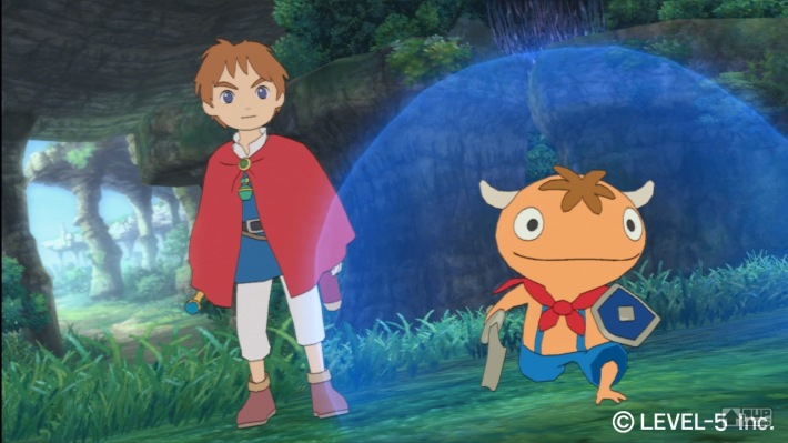
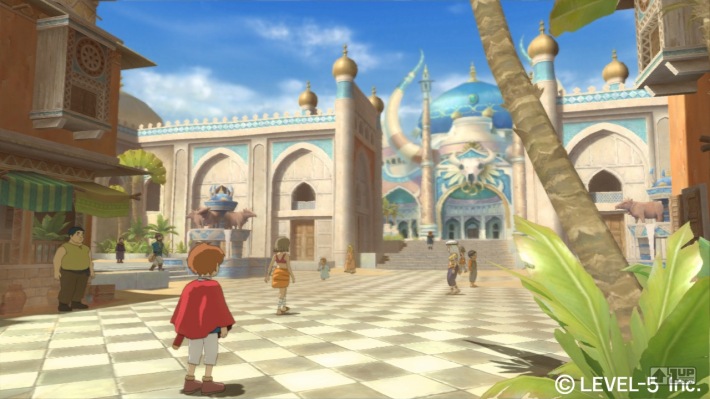
The results are a stylized and astonishing art form, take a look at these images from the recently released (in North America that is) PS3 title Ni No Kuni: Wrath of the White Witch, it’s easy to mistake this for traditional 2D animation, even when looking at it up close.

Image

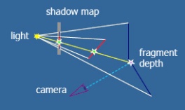
ImageWe move onto shadow mapping. Shadow mapping works in that it checks if a point is visible from the light or not. If a point is visible from the light then it’s obviously not in shadow, otherwise it is. The basic shadow mapping algorithm can be described as short as this:

Image

  1. Render the scene from the lights view and store the depths as shadow map
  2. Render the scene from the camera and compare the depths, if the current fragments depth is greater than the shadow depth then the fragment is in shadow

The implementation is difficulty however.

The two big problems with shadow mapping are that it’s hard to select an appropriate bias (epsilon) and it’s difficult to get rid of artifacts at shadow edges.

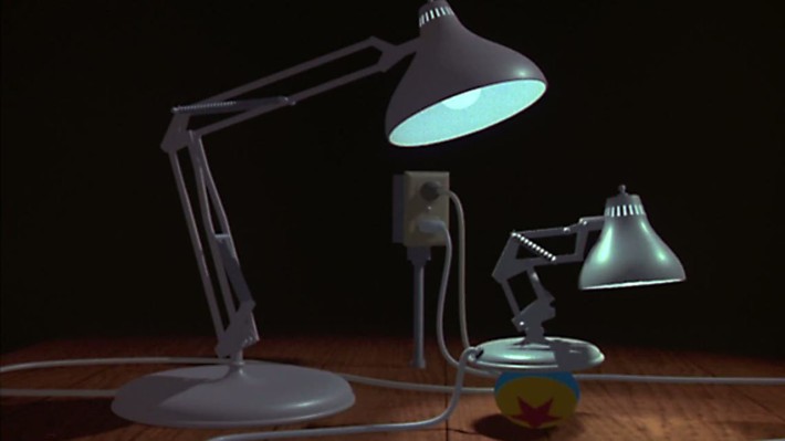
A good example of the usage of shadow mapping is the 1986 revolutionary computer-animated short film Luxo Jr. by Pixar. It was Pixar’s first animation after Ed Catmull and John Lasseter left ILM’s computer division.

ImageLasseter’s aim was to finish the short film for SIGGRAPH, an annual computer technology exhibition attended by thousands of industry professionals. Catmull and Lasseter worked around the clock, and Lasseter even took a sleeping bag into work and slept under his desk (global animation jam anyone?), ready to work early the next morning. The commitment paid off, and against all odds it was finished for SIGGRAPH. Before Luxo Jr. finished playing at SIGGRAPH, the crowd had already risen in applause.

Catmull and Smith rationalized the project as a way to test self-shadowing in the rendering software, self-shadowing is the ability of objects to shed light and shadows on themselves. On a technical standpoint, the film demonstrates the usage of shadow mapping to simulate the shifting light and shadow given by the animated lamps. The lights and the color surfaces of all the objects were calculated, each using a Renderman surface shader, not surface textures. The articulation of “limbs” is carefully coordinated, and power cords trail believably behind the moving lamps.

Tenchu Shadow Assassins: Gameplay Centered around shading and lighting

Since the genesis of video gaming, developers have aimed for the most realistic experience possible through graphics and controls given the technology. Only since recent years has technology permitted us to reach such potential. Among such technology are software such as shaders which are effects we implement in our graphics to make our environments look lively and less flat.  But shaders can benefit games in more ways than for an aesthetic choice.

Tenchu: Shadow Assassins is a 2008 stealth game released for the Playstation Portable and the Nintendo Wii. The game is centered on two ninjas, Rikimaru and Ayame carrying out missions such as retrievals or assassinations. Anyone familiar with ninja lore knows that they are well versed in the art of using their surroundings to their advantage, particularly the darkness of the shadows. This game manages to translate that well into gaming through the use of lighting and shading.

The version I have is the PSP version so that’s the version I am going to talk about. I’ve described earlier that this is a stealth game about ninjas whom are notorious for lurking in the shadows. In the game your character must sneak about undetected, this also involves sneaking behind enemies and taking them out before they know you’re there.

Image

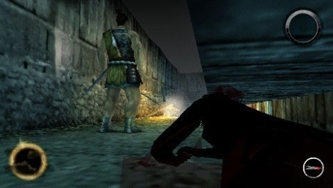
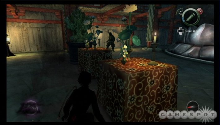
This is where the shading aspect comes in; in order for your character to sneak around, he/she needs to hide from enemy sight, among the best hiding places are shadows which are noticeably darker and to let players know they are hidden, your character becomes a silhouette to drive the point home, not to mention make it believable that enemies can’t see you. Though players still need to maneuver cautiously even in the shadows in the vicinity of an enemy, as they can still hear you if you make noise. 

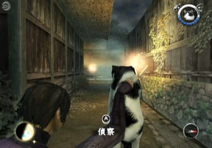
So far we talked about shading, but lighting also comes into effect. The game contains many light sources, there are a few that you can extinguish, either by blowing them out, using water, or throwing kunai or shuriken stars at them.

Image

This will create even more shadows for your character to hide in. The catch is that a lot of these light sources are close to enemies that can directly see them.

Image

But it doesn’t end there; lighting continues to play a pivotal role in the gameplay when you turn on stealth mode using the triangle button. In that mode, you can see what looks like lasers to pin point the exact direction the enemies are looking at, this is implemented for the players’ convenience in order to study their enemies’ patterns, it’s not as tedious as you may think.

So that’s Tenchu: Shadow Assassins a game that uses shading not just for its graphics, but for gameplay as well, proving that shaders are massively useful to game developers.

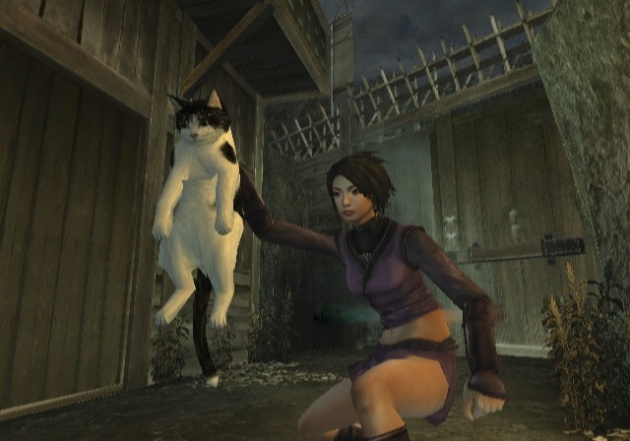
Here is your reward for reading my blog, a cat, the internet loves cats.

Image

Under the Radar: Before and After shading

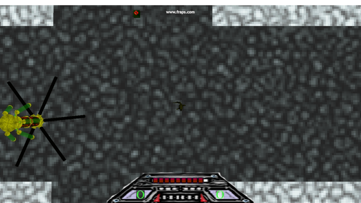
My game is called Under the Radar, it is a 2012 3D isometric adventure game. Given the limited time and limited experience of our group, the game is the bare minimum in terms of graphics. There was even a problem loading in the graphics we intended due to frame rate issues which did not allow the textures to look as good as intended or the models to move as smoothly as they could. But there is a way to improve upon the in game graphics, not just in the texturing but also the overall atmosphere.

As you can see, due to the camera angle and limited graphics, the perspective lends itself to seem rather flat, however it is more 3 dimensional in the gameplay.

Image

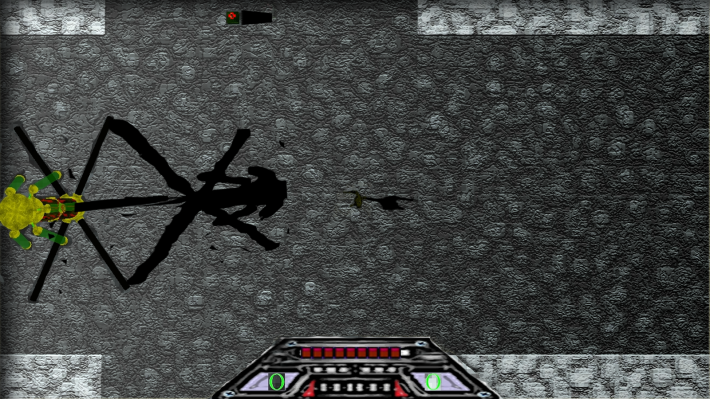
Fortunately shaders can allow us to take relatively primitive graphics and make them more appealing. What I have here is a representation of how shaders could change computer graphics.

Image

I went into the blending options, enabled the gradient overlay to make a light source appear from the left. To strengthen the effect, I added shadows to each object on the screen, in order to make accurate shadows that resemble their original hosts; I copied the image of each object, transformed the shapes to emerge from the bases of each objects’ feet, and darkened the image by turning over the lightness in Hue/Saturation to the darkest possible setting.

As mentioned earlier, the texturing does a huge disservice to the game’s graphics and makes them more dated then they are due to frame rate issues and limited time. So to make it look nicer, I used a craquelure filter to make it look like a more sophisticated stone road and structure.

Simple editing effects in photoshop helped make a flat looking image come to life and allow your sight to feast on wonderful visuals. Shaders are similar in the sense that they use simple effects to make computer graphics more appealing.

Lighting is a vital part of any game. Without lighting, everything would look incredibly flat and have no definition as shown in the screen shot of my game.

I used lighting and shaded the texture differently, this can be done in one go, two birds with one stone, using the ADS lighting model.

The ADS lighting model consists of three kinds of lights, Ambient light which is always present at all points, Diffuse light which is light coming directly from a light source, and Ambient light which is reflected by an object from the light source to give it that shiny looking texture.

Ambient Lighting is simplest one and can be seen as a global brightening factor applied to the geometry lit. Imagine light which comes from no particular location because it has bounced off the surface of objects often you can also say it comes from everywhere. This light is relatively low comparatively. It just makes absolutely dark places a bit brighter.

For example, take a Vertex which has an ambient material color of pure red, if your Ambient Lighting Color is this:

Image

To get the Ambient Color for the Vertex, just multiply these two, component wise:Image

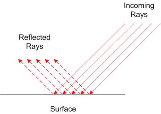
Diffuse lighting is more complex than ambient lighting. Imagine a light source which is at a far away location like the sun. Each light ray is parallel when an object is hit.

Image

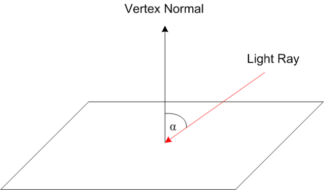
The diffuse coefficient is proportional to the input angle of the incoming rays, perpendicular to the vertex it’s value is 1, at 0° or 180° its 0. To get the angle of the incoming ray we would require the vertex normal.

Image

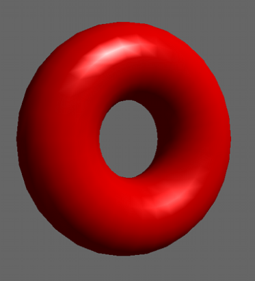
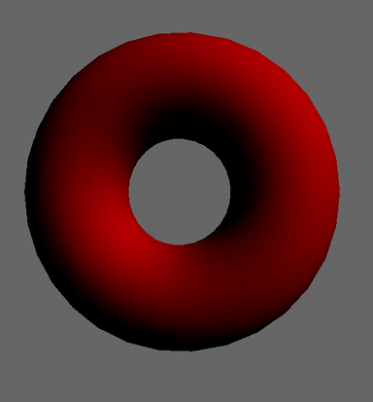
If we take a look at our torus we can clearly see far more details – this time the torus is diffusely lit only:

Image

To calculate the final diffuse color of the vertex, use the following equation:

 Image

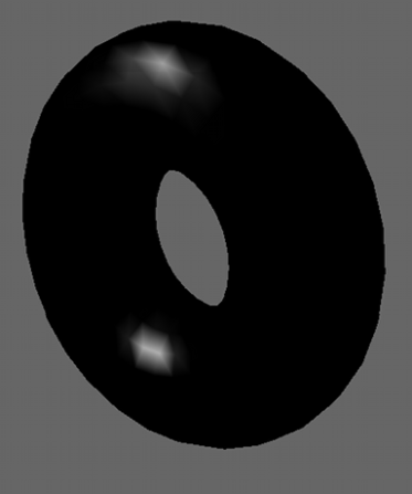
The final light type is specular lighting. Imagine something made of glossy plastic. If you look at it, you will see spots reflecting the light. This property leads us to the conclusion that specular lighting is a highly view angle and light position dependent property. Take a look:

So, here we have more properties to take care off:

  • L is the vector from the Light source to the vertex
  • N is the vertex normal
  • R is the reflected incoming Light Ray
  • C is the vector from the vertex to the viewer position
  • The shininess exponent (S), ranging from 0 (maximum reflection) to 128 (no reflection); this one isn’t shown on the graphic

To calculate the Specular coefficient use the following equation:

 Image

In the equation above you need to know the Reflection R, which is calculated by:

 Image

This type of specular light calculation is the so called “Phong” Model (there are others, but this one’s the simplest)

Seems a little bit complicated but GLSL supports us with built-in functions to calculate the reflection of a vector about another one. Last but not least, here’s an image of our torus with just the specular components:

Image

At the end of the day, when all three lights are fused together, this is the final result:

Image

It’s beautiful isn’t it? I hope to achieve this level graphics in the coming months, and hope to apply such techniques to make the nicest possible

Under the Radar -: the official game

Image

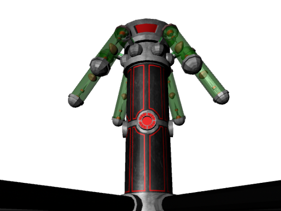
Under the Radar is a 2012 isometric adventure game design and implemented by Studio of the Beast, more commonly known as Studio 7. The story of this adventure is that the world has been taken over by a sinister alien race known as the Menrik Corps, semi-organic, semi-robotic, all sadistic. However, one champion rises above the rest to combat the alien occupation and restore liberty to his people, his name is Blake Stryx, and he is in the fight for his life, and the life of his home world.

The game was designed in adherence to the requirements for an Isometric Adventure Game, as tasking as it is we’ve managed to fulfill them. Our lead 3D artist made models with assistance from the 2D artist and Lead Designer.

Image

Under the Radar contains 5 levels, all of which contain bosses which are progressively more challenging. All the bosses are representatives of the Menrik Corps, they are the strongest of the strong.

Image

There are several weapons at Stryx’s disposal; you have a crowbar as a default weapon, guns, machine guns, grenades and a special EMP grenade.

Weapons:

–          Crowbar: default weapon

–          Gun: projectile

–          Machine gun: improvement on the normal gun

–          Grenades: to destroy enemies in a given radius

–          EMP Grenades: more destructive that its grenades

Power Ups:

–          Steroids: gives the player extra damage resistance

Image

Gameplay:

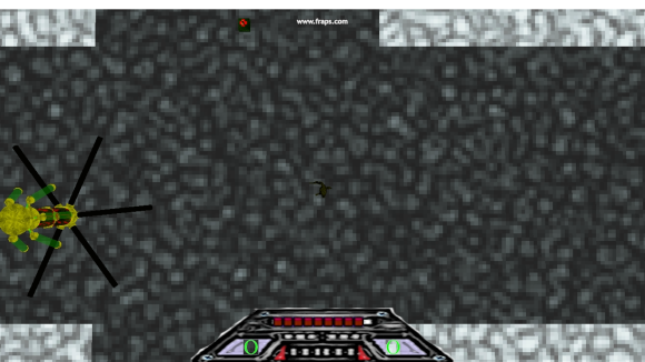
The goal of each level to reach the end of the level to fight the boss and gather the main confidence orb. It’s relatively simple, however the player will have to contend with several enemies such as Enslaved humans, flying drones, mechanized sentries and Alien Soldiers. Along with a slew of enemies, your path might be interrupted by doors and laser barriers which you must deactivate by destroying their respective power nodes.

Under the Radar :- The Board Game

Image

Studio of the Beast

Rishon Talker – 100428656

Bassem Todary – 100425868

Connor McCarthy – 100426175

Corey Best – 100454537

Adam LeDrew – 100303439

Rules

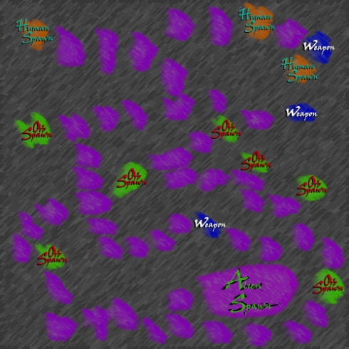
–          At the beginning of the game players split into two teams. Humans and Aliens

–          An even number of players is recommended(max 6)

–          If there are only two players, they each control two or three tokens.

–          The five Orbs are placed on the green “Orb” spaces.


Human Rules

–          First the Human players choose an orange “Human” space to start on.

–          Then their turn, they can move up to two spaces.

–          If they pass over an alien, they can choose to use an orb to send that alien back to the spawn, wounded.

–          If they pass over or land on a weapon, they flip over to the “Weapon” side.

–          If they land on an orb, they are given the orb.

–          They can’t land on another human.

–          If they pass over a human, they can trade orbs and weapons.(You can only trade weapons if one player has a weapon and one player does not. Flip both tokens)

Alien Rules

–          Aliens all start on the purple “Alien” space.

–          On their turn they can move up to three spaces. If they are a bug, they can only move one.

–          They are not allowed to land on an orb(they can land on an “Orb” space as long as the orb has already been collected), or another alien(excluding purple alien spawn and during combat)


Combat

–          If two players on opposite teams land on the same space, combat starts.

–          Each alien and bug can then move up to three spaces. If they land on the space where combat is currently happening, they are now part of combat. If they land on a player not involved with combat, that combat does not start until this one is finished.

–          Each player rolls a six sided dice.

–          All the aliens add their rolls together, and compare with the human’s roll.

–          Then the Human may remove an orb in his possession from the game, and add three to his roll.

–          He may also flip from “Weapon” to “Unarmed” to add two to his roll.

–          Then any Human that is up to five spaces away, can flip from “Weapon” to “Unarmed” to add five to the human’s roll.

–          If there is a tie, the human is able to move up to four spaces.

–          If Human wins, all Aliens involved in combat are sent to the alien spawn. If they were previously “Unharmed”, they flip to “Wounded”. If they were “Wounded” they are now an “Alien Bug”.

–          If the Aliens win, they can move up to one space, but can no longer be on the same space as another alien. Human that was rolling the die is eliminated from the game.(remove player token)

Victory Conditions

Humans

Collect all the orbs. Orbs

Aliens

Eliminate Humans