Tag Archives: 3D

The cinematics of Arkham Origins, lessons learned from making both a movie and a game

I went to MIGS this weekend and had a blast, being surrounded by all these games, as well as fellow students, upcoming developers and professionals from major studios is quite frankly a dream come true.

Image

My undisputed favorite part of the presentation by Ben Mattes of Warner Bros. games of Montreal. He talked about making a movie and a game at the same time; in which they speak about their experiences creating the cinematics of Arkham Origins.

Image

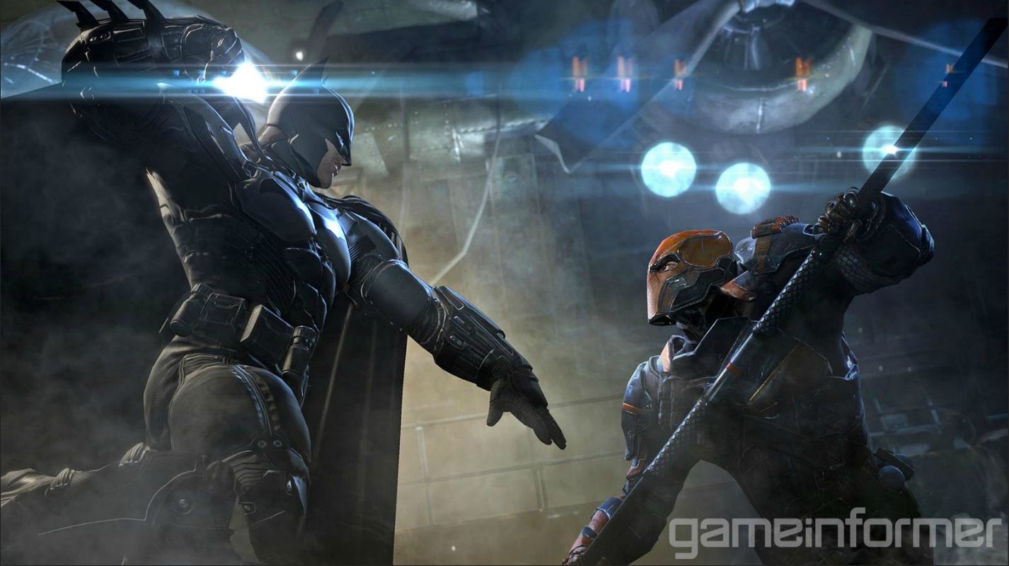
We all saw the TV spots and trailers, those CG cutscenes looked so visually amazing, I honestly thought it was a live action movie at first glance.

Image

Naturally the process was very difficult, according to their stories, they had since late last year to create everything which is a very tight schedule. That wasn’t even the worst of it. Given that they were telling a story, they naturally had to follow a script. The problem was the script wasn’t readily available to them from the start as you’d expect. No, the script was written, reviewed and approved in increments for the sake of editing flexibility, which left Mr. Mattes team at a disadvantage with the time schedule. Considering how serious WB & DC are about their character, it was not like WB games could take any liberties of the sort. Anything having to do with the story and characters begun and ended with their property owners, the rest was left to the cinematic cutscene developers.

Image

In order to properly animate the characters of the game, they made extensive use of motion capture and shot everything at a studio with an army of stuntmen and stuntwomen enacting the actions of the characters. Everything from Batman’s martial arts to Joker’s over the top body language to Copperhead’s movements was done with motion capture. On the topic of Copperhead, things like climbing on the walls were simulated with walls and rails that they built. Every movement that required some specific environment, the team built them in order to properly capture the right animations.

Indeed, they put so much effort like you wouldn’t even imagine, and of course it was a difficult task given what resources they had to gather. They had to go through the trouble of casting each motion capture actor to perfectly suit their roles, in particular they had to find a large man in order to play Bane. Developers don’t just get people off the street to do these, in order to be hired to do motion capture, you need to be a credible actor and/or stunt person. I even met one at MIGS who told me this information. Like actors in movies, motion capture actors have schedules that they and the developers need to organize. This was a huge problem for them given the issue with getting a script on time.

Image

There is a faster method to create these cutscenes, an alternative to motion capture is performance capture; which is a recording method that encompasses body motion capture, facial motion capture and voice recording. The problem is as you’d expect, it’s far too expensive.

Fortunately the long way proved to be much more ideal in the aesthetics department. With voice acting, they did it separately with expert voice actors such as Troy Barker as Joker. As for the facial rigging, they did that by using blenders, changing the facial expressions manually in maya by interpolating using catmull rom between 9 different expressions.

Image

This ended up working better because they managed to avoid Uncanny Valley and retain the exaggerated expressions of comic book characters.

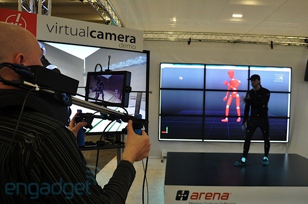
They captured all these movements with the usage of a virtual camera. But it’s not a traditional virtual camera that’s created in Maya and exported onto the engine. The animators used a portable camera that shot the motion capture set, projecting the objects and animations on a virtual space. Like a regular camera, it’s handled and moved in certain positions by a camera in order to get the exact angle they want. It’s barely different from traditional filmmaking.

Image

Arkham Origins is one of the few games this year that made use of pre-rendered cinematics which is higher quality but takes up more disk space. After all the scenes are shot they take them into the engine and composite them in order to have…..drumroll please…… SHADERS!  Adding lighting effects, dust particles and pyrotechnics to create a more lively and realistic environment.

Image

The lengths the animators took to create their cutscenes is no different from how regular films are shot; they hire actors to perform in front of a camera handled by a camera man, they need to follow the script and have to take the scenes and add effects later on in post-production. It’s uncanny how much effort they went through given the amount of obstacles they encountered, and to produce what they did at that caliber is to be commended. I think these cutscenes have better animation than most Pixar movies.

My only disappointment is not enough time to ask him questions, I had tonnes.

Ambient, Diffuse, Specular and Emissive lighting

The Light Model covers ambient, diffuse, specular, and emissive lighting. This is enough flexibility to solve a wide range of lighting situations. You refer to the total amount of light in a scene as the global illumination and compute it using the following equation.

Global Illumination = Ambient Light + Diffuse Light + Specular Light + Emissive Light

Image

Ambient Lighting is constant lighting. It is the light an object gives even in the absence of strong light. It is constant in all directions and it colors all pixels of an object the same. It is fast to calculate but leaves objects looking flat and unrealistic. 

Image

Diffuse Lighting relies on both the light direction and the object surface normal. It varies across the surface of an object because of the changing light direction and the changing surface numeral vector. It takes longer to calculate diffuse lighting because it changes for each object vertex, however the benefit of using it is that it shades objects and gives them three-dimensional depth.

Image

Specular Lighting recognizes the bright specular highlights that occur when light hits an object surface and reflects back toward the camera. It is more intense than diffuse light and falls off more rapidly across the object surface.

Image

It takes longer to calculate specular lighting than diffuse lighting, however the benefit of using it is that it adds more detail to a surface.

Image

Emissive Lighting is light that is emitted by an object such as a light bulb.

Image

Realistic lighting can be accomplished by applying each of these types of lighting to a 3D scene. The values calculated for ambient, emissive, and diffuse components are output as the diffuse vertex colour; the value for the specular lighting component is output as the specular vertex color. Ambient, diffuse, and specular light values can be affected by a light’s attenuation and spotlight factor.

To achieve a more realistic lighting effect, you add more lights; however, the scene takes a longer time to render. To achieve all the effects a designer wants, some games use more CPU power than is commonly available. In this case, it is typical to reduce the number of lighting calculations to a minimum by using lighting maps and environment maps to add lighting to a scene while using texture maps.

Lighting is computed in the camera space. Optimized lighting can be computed in model space, when special conditions exist: normal vectors are already normalized (D3DRS_NORMALIZENORMALS is True), vertex blending is not necessary, transformation matrices are orthogonal, and so forth.

For example there is the OpenGL lighting model with ambient, diffuse, specular and emissive lighting. This model is mainly used but there are many other models for lighting. In fixed-function OpenGL only this lighting model could be used, no other.

Image

With Shaders you are able to write your own lighting model. But that’s only one feature of shaders. There are thousands of other really nice possibilities: Shadows, Environment Mapping, Per-Pixel Lighting, Bump Mapping, Parallax Bump Mapping, HDR, and much more!

Shaders, the 3D photoshop Part 2

In my previous blogpost, I went over the many algorithms used in both 2D and 3D computer graphics. I talked about how they are essentially the same. We’ll use a screen shot from my game Under the Radar that I editted in photoshop, before and after respectively.

Image

Image

Drop shadowing in photoshop is the same as shadow mapping in which it checks if a point is visible from the light or not. If a point is visible from the light then it’s obviously not in shadow, otherwise it is. The basic shadow mapping algorithm can be described as short as this:

– Render the scene from the lights view and store the depths as shadow map

– Render the scene from the camera and compare the depths, if the current fragments depth is greater than the shadow depth then the fragment is in shadow

In some instances, drop shadows are used to make objects stand out of the background with a an outline, in shaders this is done with sobel edge filters.

The Sobel operator performs a 2-D spatial gradient measurement on an image and so emphasizes regions of high spatial frequency that correspond to edges. Typically it is used to find the approximate absolute gradient magnitude at each point in an input grayscale image.

In theory at least, the operator consists of a pair of 3×3 convolution kernels. One kernel is simply the other rotated by 90°. This is very similar to the Roberts Cross operator.

These kernels are designed to respond maximally to edges running vertically and horizontally relative to the pixel grid, one kernel for each of the two perpendicular orientations. The kernels can be applied separately to the input image, to produce separate measurements of the gradient component in each orientation (call these Gx and Gy). These can then be combined together to find the absolute magnitude of the gradient at each point and the orientation of that gradient.

In photoshop, filters are added to images to randomize the noise and alter the look. The equivalent in shaders is known as normal mapping. Normal maps are images that store the direction of normals directly in the RGB values of the image. They are much more accurate, as rather than only simulating the pixel being away from the face along a line, they can simulate that pixel being moved at any direction, in an arbitrary way. The drawbacks to normal maps are that unlike bump maps, which can easily be painted by hand, normal maps usually have to be generated in some way, often from higher resolution geometry than the geometry you’re applying the map to.

Normal maps in Blender store a normal as follows:

  • Red maps from (0-255) to X (-1.0 – 1.0)
  • Green maps from (0-255) to Y (-1.0 – 1.0)
  • Blue maps from (0-255) to Z (0.0 – 1.0)

Since normals all point towards a viewer, negative Z-values are not stored, also map blue colors (128-255) to (0.0 – 1.0). The latter convention is used in “Doom 3” as an example.

Those are a majority of effects that shaders use that are similar to photoshop effects, there’s also color adjustment which can be done in color to HSL shaders along with other sorts of effects.

Shaders, the 3D photoshop

The simplest way to describe shaders is that it is the photoshop of 3D graphics; both of them are used to create effects enhancing lighting and mapping, to make the images more vivid and lively, and to give bad photographers, artists and modelers a chance to redeem their miserable work.

Perhaps the greatest thing they have in common are the algorithms used to execute their operations, they’re not just similar, they’re the exact same math operations.

Image

Their primary difference is photoshop is used to manipulate 2D images and shaders alter 3D images, however both images are made up of pixels.

Image

First, the image must be processed, but how? We must define a generic method to filter the image.

Image

As you can see, all elements in the kernel MUST equal 1. We must normalize by dividing all the elements by the sum in the same way we normalize a vector.

The central element of the pixel, which in the case of what we have above is 6, will be placed all over the source pixel which will then be replaced with a weighted sum of itself and pixels nearby.

That’s how it works it works for images normally, but what about in shaders?

Normally we do forward rendering. Forward rendering is a method of rendering which has been in use since the early beginning of polygon-based 3d rendering. The scene is drawn in several passes, then the cull scene becomes renderable against frustum, then the culled Renderable is drawn with the base lighting component (ambient, light probes, etc…).

Image

The problem with shaders is that fragment/pixel shaders output a single color at a time. It does not have access to its neighbours, therefore convolution is not possible.

The first pass is stored in the Frame Buffer Object (i.e. all color is in a texture) and we can sample any pixel value in a texture!

Digital images are created in order to be displayed on our computer monitors. Due to the limits human vision, these monitors support up to 16.7 million colors which translates to 24bits. Thus, it’s logical to store numeric images to match the color range of the display. By example, famous file formats like bmp or jpeg traditionally use 16, 24 or 32 bits for each pixel.

Image

Each pixel is composed of 3 primary colours; red, green and blue. So if a pixel is stored as 24 bits, each component value ranges from 0 to 255. This is sufficient in most cases but this image can only represent a 256:1 contrast ratio whereas a natural scene exposed in sunlight can expose a contrast of 50,000:1. Most computer monitors have a specified contrast ratio between 500:1 and 1000:1.

High Dynamic Range (HDR) involves the use of a wider dynamic range than usual. That means that every pixel represents a larger contrast and a larger dynamic range. Usual range is called Low Dynamic Range (LDR).

Image

HDR is typically employed in two applications; imaging and rendering. High Dynamic Range Imaging is used by photographers or by movie maker. It’s focused on static images where you can have full control and unlimited processing time. High Dynamic Range Rendering focuses on real-time applications like video games or simulations.

Image

Since this is getting quite long, I’ll have to explain the rest in another blog. So stay tuned for part two where we will go over some of the effects of photoshop and shaders and how they’re the same as well as the algorithms behind them.