Tag Archives: Bassem

A look at abstract interface

Abstraction is about producing generalizations from certain instances. A complete abstraction can be identified by the general nature entirely, because it makes no reference to particular cases. The principle of abstraction is useful for engine developers because by designing the components of the engine to be abstract as opposed to particular so that developers increase their versatility which is proportional to their degree of abstraction.

An example of this is a render manager that may be used for all games as rendering is a vital process for every games. A text renderer manager on the other hand is less abstract and more limited in scope as it’s meant to render only text.

The main principle of abstraction encourages the engine developer to think in the abstract. To encourage them to identify many particular needs of a certain case and then proceed to expand upon it. Thus the purpose of abstraction is to increase versatility of engines.

An interface is not a class. It is an entity that is defined by the word Interface. An interface doesn’t have implementation; it only has the definition of the methods without the body. Similar to the abstract class, it is a contract that is used to define hierarchies for all subclasses or it defines specific set of methods and their arguments. The main difference between them is that a class can implement more than one interface but can only inherit from one abstract class. Since C# doesn’t support multiple inheritance, interfaces are utilized to implement multiple inheritance.

When we create an interface, we are basically creating a set of methods without any implementation that must be overridden by the implemented classes. They are used to define the peripheral abilities of a class. When it comes to features like multiple inheritance, a class may inherit several interfaces. Default implementation dictates that an interface cannot provide code, only signatures. Similarly they can access modifiers for the functions and properties with access modifiers, as everything is assumed as public.

If various implementations only share method signatures, it is recommended to use Interfaces as they are more efficient in this regard. If a new method is added to an Interface then we have to track down all the implementations of the interface and define implementation for the new method. A drawback is that they require more time to find the actual method and no field can be defined in interfaces.

More on Havok, physics and collision

What is the most important aspect of a video game? That’s something that has been debated since the inception of video games, and said question could be applied to its technological, spiritual predecessor which are sports, board games and other sorts of games. Every individual has their own opinion on the matter, and my personal opinion is that the most vital fundamental aspect of any game is interactivity; the point where the player’s choices and the game’s mechanics meet on mutual ground and develop an agreement. All games have rules that allow players certain freedoms and limitations, the player’s enjoyment essentially comes down to what state of mind these boundaries put them in.

Last week we made a very general observation of the Havok physics engine. This relates to my thesis statement as physics are an integral part of a games internal logic; the ability to move your character and do any other action is part of your freedoms, whilst falling in chasms and not penetrating walls makes up your limitations.

Collision detection is important for every game in that regard. Take away any form of collision and every object would fall through the ground with the ground itself, making any form of interaction impossible, unless you’re making a kill screen, this is not a reasonable programming design.

Collision and physics are more often than not a tightly knit pair. This is because at the moment collisions are detected, they are always resolved as part of the engine’s logic in physics and constraint integration.

The purpose of collision in a game engine is to determine whether any of the objects in the game’s world are in contact. In order to properly address this, each logical object is represented by geometric shapes. The collision system of the engine determines whether or not these specific shapes are intersection, which means that the collision detection is system is nothing more than a geometric intersection tester.

Collision systems are more than a true or false question regarding shape intersection. Its purpose is to provide relevant information about each contact. That information can be used to prevent unrealistic visual anomalies on screen. For example, last weekend at game jam, I coded an invisible border at the end of the level to go to the game over screen, an example of collision utilized to convey certain information on screen through the programming interface.

This information is used to prevent on-screen anomalies by moving the interpenetrating objects apart prior to rendering the next frame. They can also provide support for an object, such as an object at rest on the ground thanks to the force of gravity on the geometric shape of the ground acting upon it.

Indeed collisions essentially make up most of the gameplay. Think about it; coming into contact with a health power up, shooting at an object to destroy it, even being on the ground is a form of collision. Collision is the main fundamental aspect of interactivity in games, it supports nearly all of the player functions while fulfilling the main objective of the game, to enforce an experience on players.

A brief overview of the Havok Physics Engine

At 2K Czech, games demanded a physics solution that can scale efficiently and handle highly detailed interactive environments. Having recently moved to the next generation of Havok Physics, Havok’s new physics technology is able to make highly efficient utilization of all available hardware cores with a very lean runtime memory footprint. This combination allows us to deliver the high quality simulation at the scale we need and we are really looking forward to making some incredible games with the new technology.” -Laurent Gorga, Technical Director at 2K Czech.

Laurent Gorga, 2K Czech’s Technical Director, further added that “At 2K Czech, our games demand a physics solution that can scale efficiently and handle highly detailed interactive environments. Having recently moved to the next generation of Havok Physics, we’ve been blown away by how Havok’s new physics technology is able to make highly efficient utilization of all available hardware cores with a very lean runtime memory footprint.”

Developed by the Irish company Havok, the eponymous Havok Physics is a physics engine designed for video games to allow for real-time interaction between objects in 3D. The engine uses dynamic simulation to allow for ragdoll physics. The company was founded by Hugh Reynolds and Dr. Steven Collins in 1998 in Trinity College Dublin where much of its development is still carried out. Dr. Steven Collins currently acts as course director to Interactive Entertainment Technology in Trinity College Dublin, as well as lecturing in real-time rendering. Havok can also be found in Autodesk 3ds Max as a bundled plug-in called Reactor. A plugin for Autodesk Maya animation software and an extra for Adobe Director’s Shockwave are also available.

As a result Havok offers the fastest and most robust collision detection and physical simulation technology available, which is why it has become the ideal physics engine to go to within the games industry and has been used by leading game developers in over 400 launched titles and many more in development.

Havok Physics is fully multi-threaded and cross-platform optimized for leading game platforms including, Xbox 360™, Playstation® 4, PlayStation®3 computer entertainment system, PC Games for Windows, PlayStation Vita®, Wii™, Wii U™, Android™, iOS, Apple Mac OS and Linux.

In 2008 Havok released details of its new Cloth and Destruction middleware. Cloth deals with simulation of character garments and soft bodies while Destruction provides tools for creation of destructible and deformable environments. Havok Cloth was the company’s most widely adopted and bestselling piece of software to date.

At GDC 2009 Havok showcased the first details of its forth coming artificial intelligence tools which will allow for better performing AI in games without the need for the developers to create their own AI models.

Whenever people say “Havok Physics”, all I can think of is The Elder Scrolls: Oblivion.  One of its major selling points was Havok Physics.  Anyone who has played that game knows how messed up Havok Physics can get, and how silly of situations you can create with it. Grand Theft Auto 4 also uses Havok Physics.

It was also used throughout the Halo games from Halo 2 onwards. In the Halo 3 engine The Halo 3 physics engine runs calculations on every single frame of animation, similarly to the collision detection engine. The engine is capable of calculating, among other things, elasticity on portions of character models; and bullet ricochet.

Character models are quite elastic at points, a characteristic that is clearly demonstrated by the Character Stretch Glitch’s presence in the game. The elasticity helps to improve realism at slower speeds. Only some parts of a character’s model are elastic; if you look closely at screenshots of the aforementioned glitch, you will find that the rigid parts of Spartans’ and Marines’ armor don’t stretch.

The physics engine utilizes an optimization found in many video game physics engines: objects that remain at rest for several seconds are temporarily exempted from physics calculations (but not collision detection) until they are disturbed again; this is why floating Crates and Fusion coils can remain floating in the air until the round is restarted or the items are disturbed. An object is considered “disturbed” if it is moved, picked up (in Forge), or if something collides with it.[5] The optimization is likely based on the premise that an object that isn’t moving now isn’t likely to move in the near future unless something moves it or it moves on its own.

Havok has announced the launch of the third major iteration to its Havok Physics technology that features “significant technical innovations” in performance, memory utilization, usability, and is a “major leap forward” for in-game physics simulation. The release is specifically targeted towards next-generation consoles, mobile devices, and PCs with full compatibility and support for current devices.

According to Andew Bond, Vice President of Technology for Havok, this version has resulted in a “new engine core built around fully continuous simulation that enables maximum physical fidelity with unprecedented performance speeds. Beta versions of the technology have been in the hands of a number of leading developers for some time and we have seen dramatic performance gains with simulations running twice as fast or more, and using up to 10 times less memory. Additionally the new core’s performance is extremely predictable, eliminating performance spikes.”

Usages of bloom and blur in games

Bloom, which is also called light bloom or glow, is a computer graphics effect used in video games, demos and high dynamic range rendering (HDR) to reproduce an imaging artifact of real-world cameras. The effect produces fringes (or feathers) of light extending from the borders of bright areas in an image, contributing to the illusion of an extremely bright light overwhelming the camera or eye capturing the scene.

Image

The physical basis of bloom is that lenses can never focus perfectly, even a perfect lens will convolve the incoming image with an Airy disc, the diffraction pattern produced by passing a point light source through a circular aperture. Under normal circumstances, these imperfections are not noticeable, but an intensely bright light source will cause the imperfections to become visible. As a result, the image of the bright light appears to bleed beyond its natural borders.

Image

The Airy disc function falls off very quickly but has very wide tails. As long as the brightness of adjacent parts of the image are roughly in the same range, the effect of the blurring caused by the Airy disc is not particularly noticeable; but in parts of the image where very bright parts are adjacent to relatively darker parts, the tails of the Airy disc become visible, and can extend far beyond the extent of the bright part of the image.

In HDR images, the effect can be re-produced by convolving the image with a windowed kernel of an Airy disc, or by applying Gaussian blur to simulate the effect of a less perfect lens, before converting the image to fixed-range pixels.

Image

The effect cannot be fully reproduced in non-HDR imaging systems, because the amount of bleed depends on how bright the bright part of the image is.

As an example, when a picture is taken indoors, the brightness of outdoor objects seen through a window may be 70 or 80 times brighter than objects inside the room. If exposure levels are set for objects inside the room, the bright image of the windows will bleed past the window frames when convolved with the Airy disc of the camera being used to produce the image.

Image

Current generation gaming systems are able to render 3D graphics using floating point frame buffers, in order to produce HDR images. To produce the bloom effect, the HDR images in the frame buffer are convolved with a convolution kernel in a post-processing step, before converting to RGB space. The convolution step usually requires the use of a large Gaussian kernel that is not practical for realtime graphics, causing the programmers to use approximation methods.

Ico was one of the first games to use the bloom effect. Bloom was popularized within the game industry in 2004, when an article on the technique was published by the authors of Tron 2.0. Bloom lighting has been used in many games, modifications, and game engines such as Quake Live, Cube 2: Sauerbraten and the Spring game engine. The effect is popular in current generation games, and is used heavily in PC, Xbox 360 and PlayStation 3 games as well as Nintendo GameCube and Wii releases such as The Legend of Zelda: Twilight Princess, Metroid A Gaussian blur is one of the most useful post-processing techniques in graphics yet I somehow find myself hard pressed to find a good example of a Gaussian blur shader floating around on the interwebs. The theory behind its value generation can be found in GPU Gems 3; Chapter 40 (“Incremental Computation of the Gaussian” by Ken Turkowski).Prime, and Metroid Prime 2: Echoes.

Deferred Rendering

Deferred rendering is an alternative to rendering 3d scenes. The classic rendering approach involves rendering each object and applying lighting passes to it. So, if an object is affected by 6 lights, it will be rendered 6 times, once for each light, in order to accumulate the effect of each light. This approach is referred forward rendering. Deferred rendering takes another approach: first of all of the objects render their lighting related information to a texture, called the G-Buffer.

Image

This includes their colours, normals, depths and any other info that might be relevant to calculating their final colour. Afterwards, the lights in the scene are rendered as geometry (sphere for point light, cone for spotlight and full screen quad for directional light), and they use the G-buffer to calculate the colour contribution of that light to that pixel.

The motive for using deferred rendering is mainly performance related – instead of having a worst case batch count of objects by the amount of lights (if all objects are affected by all lights), you have a fixed cost of objects and lights. There are other pros and cons of the system, but the purpose of this article is not to help decide whether deferred rendering should be used, but how to do it if selected.

Image

The main issue with implementing deferred rendering is that you have to do everything on your own. The regular rendering approach involves rendering each object directly to the output buffer (called ‘forward rendering’). This means that all of the transform & lighting calculations for a single object happen in a single stage of the process. The graphics API that you are working with exposes many options for rendering objects with lights. This is often called the ‘fixed function pipeline’, where you have API calls that control the fashion in which an object is rendered. Since we are splitting up the rendering to two parts, we can’t use these faculties at all, and have to re-implement the basic (and advanced) lighting models ourselves in shaders.

Image

Even shaders written for the forward pipeline won’t be usable, since we use an intermediate layer (the G-Buffer). They will also need to be modified to write to the G-Buffer / read from the G-buffer (usually the first). In addition to that, the architecture of the rendering pipeline changes – objects are rendered regardless of lights, and then geometric representations of the light’s affected area have to be rendered, lighting the scene.

The Goal is to create a deferred rendering pipeline that is as unobtrusive as possible – we do not want the users of the engine to have to use it differently because of the way that its rendered, and we really don’t want the artists to change the way they work just because we use a deferred renderer. So, we want an engine that can:

The material system that stores all of the information that is required to render a single object type besides the geometry. Links to textures, alpha settings, shaders etc. are stored in an object’s material. The common material hierarchy includes two levels:

Technique – When an object will be rendered, it will use exactly one of the techniques specified in the material. Multiple techniques exist to handle different hardware specs (If the hardware has shader support use technique A, if not fall back to technique B), different levels of detail (If object is close to camera use technique ‘High’, otherwise use ‘Low’). In our case, we will create a new technique for objects that will get rendered into the G-buffer.

Image

Pass – An actual render call. A technique is usually not more than a collection of passes. When an object is rendered with a technique, all of its passes are rendered. This is the scope at which the rendering related information is actually stored. Common objects have one pass, but more sophisticated objects (for example detail layers on the terrain or graffiti on top of the object) can have more.

Image

Examples of material systems outside of Ogre are Nvidia’s CGFX and Microsoft’s HLSL FX. Render Queues / Ordering System: When a scene full of objects is about to be rendered, all engines need some control over render order since semi-transparent objects have to be rendered after the opaque ones in order to get the right output. Most engines will give you some control over this, as choosing the correct order can have visual and performance implications:

less overdraw = less pixel shader stress = better performance,

 Image

Full Scene / Post Processing Framework: This is probably the most sophisticated and least common of the three, but is still common. Some rendering effects, such as blur and ambient occlusion, require the entire scene to be rendered differently. We need the framework to support directives such as “Render a part of the scene to a texture”, “Render a full screen quad”, allowing us to control the rendering process from a high perspective.

Generating the G-Buffer:

So we know what we want to do, we can now start creating a deferred rendering framework on top of the engine. The problem of deferred rendering can be split up into two problems – creating the G-Buffer and lighting the scene using the G-Buffer. We will tackle both of them individually.


Deciding on a Texture Format:

The first stage of the deferred rendering process is filling up a texture with intermediate data that allows us to light the scene later. So, the first question is, what data do we want? This is an important question – it is the anchor that ties both stages together, so they both have to synchronized with it. The choice has performance (memory requirements), visual quality (accuracy) and flexibility (what doesn’t get into the G-Buffer is lost forever) implications.

Image

We chose two RGBA textures, essentially giving us eight 16 bit floating point data members. It’s possible to use integer formats as well. The first one will contain the colour in RGB, specular intensity in A. The second one will contain the view-space-normal in RGB (we keep all 3 coordinates) and the (linear) depth in A.

Ambient, Diffuse, Specular and Emissive lighting

The Light Model covers ambient, diffuse, specular, and emissive lighting. This is enough flexibility to solve a wide range of lighting situations. You refer to the total amount of light in a scene as the global illumination and compute it using the following equation.

Global Illumination = Ambient Light + Diffuse Light + Specular Light + Emissive Light

Image

Ambient Lighting is constant lighting. It is the light an object gives even in the absence of strong light. It is constant in all directions and it colors all pixels of an object the same. It is fast to calculate but leaves objects looking flat and unrealistic. 

Image

Diffuse Lighting relies on both the light direction and the object surface normal. It varies across the surface of an object because of the changing light direction and the changing surface numeral vector. It takes longer to calculate diffuse lighting because it changes for each object vertex, however the benefit of using it is that it shades objects and gives them three-dimensional depth.

Image

Specular Lighting recognizes the bright specular highlights that occur when light hits an object surface and reflects back toward the camera. It is more intense than diffuse light and falls off more rapidly across the object surface.

Image

It takes longer to calculate specular lighting than diffuse lighting, however the benefit of using it is that it adds more detail to a surface.

Image

Emissive Lighting is light that is emitted by an object such as a light bulb.

Image

Realistic lighting can be accomplished by applying each of these types of lighting to a 3D scene. The values calculated for ambient, emissive, and diffuse components are output as the diffuse vertex colour; the value for the specular lighting component is output as the specular vertex color. Ambient, diffuse, and specular light values can be affected by a light’s attenuation and spotlight factor.

To achieve a more realistic lighting effect, you add more lights; however, the scene takes a longer time to render. To achieve all the effects a designer wants, some games use more CPU power than is commonly available. In this case, it is typical to reduce the number of lighting calculations to a minimum by using lighting maps and environment maps to add lighting to a scene while using texture maps.

Lighting is computed in the camera space. Optimized lighting can be computed in model space, when special conditions exist: normal vectors are already normalized (D3DRS_NORMALIZENORMALS is True), vertex blending is not necessary, transformation matrices are orthogonal, and so forth.

For example there is the OpenGL lighting model with ambient, diffuse, specular and emissive lighting. This model is mainly used but there are many other models for lighting. In fixed-function OpenGL only this lighting model could be used, no other.

Image

With Shaders you are able to write your own lighting model. But that’s only one feature of shaders. There are thousands of other really nice possibilities: Shadows, Environment Mapping, Per-Pixel Lighting, Bump Mapping, Parallax Bump Mapping, HDR, and much more!

Screen Space Ambient Occlusion – Application in games

I’ve been working on a screen space ambient occlusion code for a few weeks and I’ve managed to get a working project going, so I feel I’m qualified to talk about it. So let us begin. In computer graphics, ambient occlusion attempts to approximate the way light radiates in real life, especially off what are normally considered non-reflective surfaces. Like in my example here:

Image

Unlike conventional methods such as Phong shading, ambient occlusion is a global method, meaning the illumination at each point is a function of other geometry in the scene. However, it is a very crude approximation to full global illumination. The soft appearance achieved by ambient occlusion alone is similar to the way an object appears on an overcast day.

The first major game title with Ambient Occlusion support was released in 2007, yes, we’re talking about Crytek’s Crysis 1. Then we have it’s sequel Crysis 2 as shown here:

 Image

It’s a really cheap approximation to real ambient occlusion, it’s used in many games. It is cheap, although it does draw out a significant overhead compared to running without SSAO on. Mafia II churns out 30-40 fps when I turn on AO on max settings without PhysX, but when I turn AO off it’s silky-smooth at 50-75.

Without ambient occlusion:

Image

Screen space ambient occlusion is improved in Crysis 2 with higher quality levels based on higher resolution and two passes while the game’s water effects – impressive on all platforms – are upgraded to full vertex displacement on PC (so the waves react more realistically to objects passing into the water). Motion blur and depth of field also get higher-precision upgrades on PC too.

With ambient occlusion, note the presence of darker areas. 

Image

 While there may only be three different visual settings, it’s actually surprising just how low the graphics card requirement is to get a decent experience in Crysis 2. In part, PC owners have the console focus to thank here – Crytek’s requirement of supporting the game on systems with limited GPUs and relatively tiny amounts of RAM required an optimisation effort that can only benefit the computer version.

According to the developer, the base hardware is a 512MB 8800GT: an old, classic card that’s only really started to show its age in the last year or so. On the lowest setting (which is still a visual treat), this is still good for around 30-40FPS at lower resolutions such as 720p and 1280×1024. If you’re looking for decent performance at 1080p, a GTX260 or 8800GTX is recommended while 1080p60 at the Extreme level really requires a Radeon HD 6970 or GTX580.

In terms of the CPU you’ll need, things have definitely moved on from the days of the original Crysis, where the engine code was optimised for dual-core processors. Crysis 2 is quad-core aware, and while it runs perfectly well with just the two cores, ideally you should be targeting something along the lines of a Q6600 or better.

Nowadays we have a bunch of DX10 & DX11 games that make use of Ambient Occlusion natively ( via their own engine ), Crysis 2, Aliens vs Predator 3, BattleField 3, Gears of War 2, etc.

Still, there are several new titles without Ambient Occlusion support, and also older games that would benefit from it. nVIDIA came to the rescue a couple of years ago with an option to force Ambient Occlusion on various games by enabling the corresponding option in their drivers Control Panel.

Initially you could only choose from “Off” and “On”, but from the 25x.xx drivers and on you have three options to choose from, “Off”, “Performance” which balances the effect’s application to enhance your image while keeping the performance numbers relatively close to what you had without A.O. enabled, and “Quality”, this option sacrifices performance, often at a massive rate, but gives you the best image quality you can achieve with A.O.

As a result of extensive testing of all 3 settings of Ambient Occlusion in a couple of games, this is our result:

Ambient occlusion is related to accessibility shading, which determines appearance based on how easy it is for a surface to be touched by various elements (e.g., dirt, light, etc.). It has been popularized in production animation due to its relative simplicity and efficiency. In the industry, ambient occlusion is often referred to as “sky light”.[citation needed]

The Terrain Ambient Occlusion system controls the amount of ambient light in a scene. For example, a dense forest has less ambient light near the ground because most of the light is stopped by the trees. In the current implementation, occlusion information is stored in textures and the effect is applied to the scene in a deferred way.

The images below show the difference (in a scene) when Terrain Ambient Occlusion is enabled and when it is not.


The ambient occlusion shading model has the nice property of offering better perception of the 3d shape of the displayed objects. This was shown in a paper where the authors report the results of perceptual experiments showing that depth discrimination under diffuse uniform sky lighting is superior to that predicted by a direct lighting model.

High 32 is highest smooth frame rate (steady 60fps) that I’ve found while testing with a MSI GTX 680 Lightning.

 ImageImage

What are we looking at here? Alright, the best example is the vase held up to the candle. Notice the blurry yet real time shadow effect which is cast behind the vase? There you go, that’s SSAO in Amnesia. The thing is SSAO is entirely dependent on angle: if you were to stand behind the vase the shadow wouldn’t show up yet the vase would have a black glow to it. The bookcase, the fireplace and the dresser show other examples of SSAO effects you’ll see throughout the game. SSAO maxed out on High/128 killed my framerate down to 14 FPS and there was little difference compared to the much more playable setting at Medium/64. Overall, the game looks better with some form of SSAO enabled. In some areas it made things look engulfed in some ugly blurry black aura. Still, a good feature to have in a game that uses shadows for its overall atmosphere and I appreciate the effect SSAO tries to achieve yet I think it does a pretty sloppy job at emulating ‘darkness’. Setting this setting maxed out isn’t a good idea either, you’ll actually get less “black glowing” if it’s set to around 16/32. Now if only they had some form of Anti-Aliasing to play with.

The occlusion at a point on a surface with normal can be computed by integrating the visibility function over the hemisphere with respect to projected solid angle as shown below:


where  is the visibility function at , defined to be zero if  is occluded in the direction  and one otherwise, and  is the infinitesimal solid angle step of the integration variable . A variety of techniques are used to approximate this integral in practice: perhaps the most straightforward way is to use the Monte Carlo method by casting rays from the point  and testing for intersection with other scene geometry (i.e., ray casting). Another approach (more suited to hardware acceleration) is to render the view from  by rasterizing black geometry against a white background and taking the (cosine-weighted) average of rasterized fragments. This approach is an example of a “gathering” or “inside-out” approach, whereas other algorithms (such as depth-map ambient occlusion) employ “scattering” or “outside-in” techniques.

Along with the ambient occlusion value, a bent normal vector is often generated, which points in the average direction of samples that aren’t occluded. The bent normal can be used to look up incident radiance from an environment map to approximate image-based lighting. However, there are some situations in which the direction of the bent normal doesn’t represent the dominant direction of illumination.


So that’s SSAO in a nutshell, it was quite difficult to understand let alone implement due to the amount of calculations, as well as the fact that is puts heavy burdens on your processor. But like since the beginning, games sought to be as realistic as possible in order to uphold its role as a medium that immerses players into experience. Screen Space Ambient Occlusion is another means of doing to simulate the nature of lights and shadows. 

Vertex Buffer Objects, Frame Buffer Objects and Geometry shaders

The modern use of “shader” was introduced to the public by Pixar with their “RenderMan Interface Specification, Version 3.0” originally published in May, 1988.

Image

As graphics processing units evolved, major graphics software libraries such as OpenGL and Direct3D began to support shaders. The first shader-capable GPUs originally only supported pixel shading, but vertex shaders were then introduced when developers realized the power of shaders and sought to take advantage of its potential. Geometry shaders were only fairly recently introduced with Direct3D 10 and OpenGL 3.2, but are currently supported only by high-end video cards.

Geometry in a complete three dimensional scene is lit according to the defined locations of light sources, reflection, and other surface properties. Some hardware implementations of the graphics pipeline compute lighting only at the vertices of the polygons being rendered.

Image

The lighting values between vertices are then interpolated during rasterization. Per-fragment or per-pixel lighting, as well as other effects, can be done on modern graphics hardware as a post-rasterization process by means of a shader program. Modern graphics hardware also supports per-vertex shading through the use of vertex shaders.

Shaders are simple programs that describe the traits of either a vertex or a pixel. Vertex shaders describe the traits such as position, texture coordinates and colors of a vertex, while pixel shaders describe color, z-depth and the alpha value of a fragment. A vertex shader is called for each vertex in a primitive often after tessellation; thus one vertex in, one updated vertex out. Each vertex is then rendered as a series of pixels onto a surface that will be transported to the screen.

Shaders replace a section of video hardware often referred to as the Fixed Function Pipeline (FFP) – so-called because it performs lighting and texture mapping in a hard-coded manner. Shaders provide a programmable alternative to this hard-coded approach for the convenience of the programmers seeking to manage their code better.

Image

The CPU sends instructions (compiled shading language programs) and geometry data to the graphics processing unit, located on the graphics card. In the vertex shader, the geometry is transformed.If a geometry shader is in the graphic processing unit and active, some changes of the geometries in the scene are performed. If a tessellation shader is activated in the graphic processing unit and active, the geometries in the scene can be subdivided.

The calculated geometry is triangulated as the triangles are broken down into fragment quads (one fragment quad is a 2 × 2 fragment primitive). Fragment quads are modified according to the pixel shader, then the depth test is executed, fragments that pass will get written to the screen and might get blended into the frame buffer. The graphic pipeline uses these steps in order to transform three dimensional (and/or two dimensional data into useful two dimensional data for displaying. In general, this is a large pixel matrix or “frame buffer”.

Image

Vertex shaders are passed through once for each vertex given to the graphics processor. The purpose is to transform each vertex’s 3D position in virtual space to the 2D coordinate at which it appears on the screen (as well as a depth value for the Z-buffer).

Image

Vertex shaders are capable of altering properties such as position, color, and texture coordinates, but cannot create new vertices like geometry shaders can. The output of the vertex shader goes to the next stage in the pipeline, which is either a geometry shader if present, or the pixel shader and rasterizer otherwise. Vertex shaders can enable powerful control over the details of position, movement, lighting, and color in any scene involving 3D models.

Geometry shaders are a relatively new type of shader, introduced in Direct3D 10 and OpenGL 3.2; formerly available in OpenGL 2.0+ with the use of extensions. This type of shader can generate new graphics primitives, such as points, lines, and triangles, from those primitives that were sent to the beginning of the graphics pipeline.

Image

Geometry shader programs are executed after vertex shaders. They take as input a whole primitive, possibly with adjacency information. For example, when operating on triangles, the three vertices are the geometry shader’s input. The shader can then emit zero or more primitives, which are rasterized and their fragments ultimately passed to a pixel shader.

Typical uses of a geometry shader include point sprite generation, geometry tessellation in which you cover a surface with a pattern of flat shapes so that there are no overlaps or gaps, shadow volume extrusion where the edges forming the silhouette are extruded away from the light to construct the faces of the shadow volume, and single pass rendering to a cube map. A typical real world example of the benefits of geometry shaders would be automatic mesh complexity modification. A series of line strips representing control points for a curve are passed to the geometry shader and depending on the complexity required the shader can automatically generate extra lines each of which provides a better approximation of a curve.

Image

Pixel shaders, which are also known as fragment shaders, compute color and other attributes of each fragment. Pixel shaders range from always outputting the same color, to applying a lighting value, to performing bump mapping, specular highlights, shadow mapping, translucency and other amazing feats of rendering as shown here.

Image

They can alter the depth of the fragment for Z-buffering, or output more than one color if multiple render targets are active. In 3D graphics, a pixel shader alone cannot produce very complex effects, because it operates only on a single fragment, without knowledge of a scene’s geometry. However, pixel shaders do detect and acknowledge the screen coordinate being drawn, and can sample the screen and nearby pixels if the contents of the entire screen are passed as a texture to the shader. This technique can enable a wide variety of 2D postprocessing effects, such as blur, or edge detection/enhancement for cartoon/cel shading. Pixel shaders may also be applied in intermediate stages to any two-dimensional images in the pipeline, whereas vertex shaders always require a 3D model. For example, a fragment shader is the only type of shader that can act as a postprocessor or filter for a video stream after it has been rasterized.

God of War III’s graphics engine and various implementation

I’ve been playing a lot of God of War III lately and thanks to my Intermediate Computer graphics course, I couldn’t help but consider all the shaders being used. In God of War III, details  in terms of texturing and geometry is not just another step in graphics rendering, but one giant leap for the industry in terms of technology.

Image

Programmable pixel shaders add textures and effects that give a whole new dimension to the quality of the final work. It’s a true generational leap, and performance of the new game, in terms of frame-rate, is in the same ballpark as the previous two God of War titles.

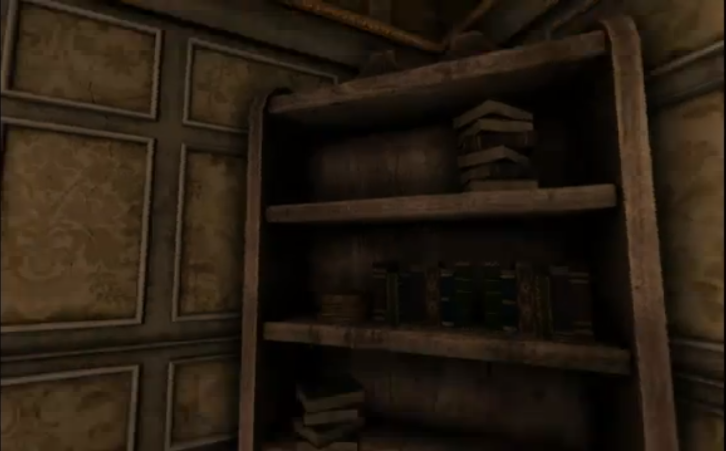
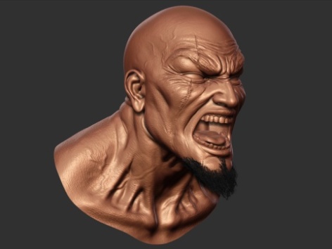
In terms of the character creations themselves, concept art and a low-poly mesh from Maya is handed off to the 3D modellers, who create the basic models using a sculpting tool known as Z-Brush. These models are then given detail – painted in via Photoshop – before being passed along the next stages in the art pipeline to the character riggers and animators.

Image

Kratos himself is a very detailed model, it’s interesting to note that the raw polygon count is considerably lower than the 35,000 or so that comprise the in-game model of Drake in Uncharted 2. But it is significantly higher than Kratos on the PS2 when he had only 5,000 polygons. He had about three textures on the PlayStation 2 and I think he has at least 20 textures on him now. The animation data on him is probably about six times as big.

Image

Kratos is a big guy but did you know that given the intricacy of his model, it would take two Playstation 2’s to fit his memory? That’s not even counting all his weapons that he has to alternate between, eat your heart out Link.

Image

Each character gets a normal, diffuse, specular, gloss (power map), ambient occlusion, and skin shader map. Layered textures were used to create more tiling, and use environment maps where needed.

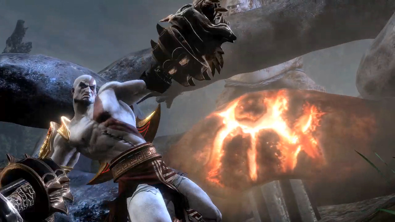
A new technique known as blended normal mapping adds to the realism of the basic model and hugely enhances the range of animation available. Muscles move convincingly, facial animations convey the hatred and rage of Kratos in a way we’ve never seen before.

The system operates to such a level of realism that wrinkles in the character’s skin are added and taken away as joints within the face of the model are manipulated. The musculature simulation is so accurate that veins literally pop into view on Kratos’s arms as he moves them around.

In terms of character movements, over and above the pre-defined animations created by the team, the God of War technical artists also created secondary animation code. Why hand-animate hair, or a serpent’s tail, when the PS3 itself can mathematically calculate the way it should look? The system’s called Dynamic Simulation; and its effects are subtle but remarkable, accurately generating motion that previously took the animators long man-hours to replicate.

From God of War II to God of War III they’ve used Dynamic Simulation more and more to do more secondary animations on the characters. Before, in previous games, the hair or the cloth would be stiff, it would be modelled into the creatures, but now they actually adding motion to those pieces so you will see hair and cloth moving.”

“Towards the end of the previous game, in collaboration with Jason Minters, I created this dynamic system that uses the Maya hair system to drive a series of joints,” adds technical artist Gary Cavanaugh. “Each of the snakes on the gorgon’s head is independently moving. The animator did not have to individually pose all of these animations but they do have control over the physics… it improves a lot of the workflow for animators.”

The tech art team bridges the gap between artists and coders. The ‘zipper tech’ tool on the left shows how they create animated wounds with belching guts, while the shot on the right shows a bespoke animation rig for the gorgon’s tail.

One of the most crucial elements of the cinematic look of God of War III is derived from the accomplished camerawork. Similar to previous God of War epics – and in contrast to Uncharted 2 – the player actually has very little control over the in-game viewpoint. Instead, Sony Santa Monica has a small team whose job it is to direct the action, similar to a movie’s Director of Photography.

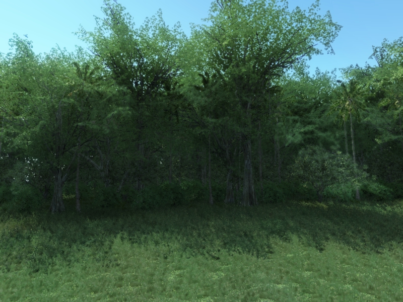
Think about it: so long as the gameplay works, and works well, having scripted camera events ensures that the player gets the most out of the hugely intricate and beautifully designed art that the God of War team has put together. When running from point A to point B, why focus the camera on a piece of ground and wall when instead it can pan back to reveal a beautiful, epic background vista?

Perhaps most astonishingly of all, the final God of War III executable file that sits on that mammoth Blu-ray is just 5.3MB in size – uncompressed, and including SPU binaries – in a project that swallows up a mammoth 35GB of Blu-ray space (40.2GB for the European version with its support for multiple languages).

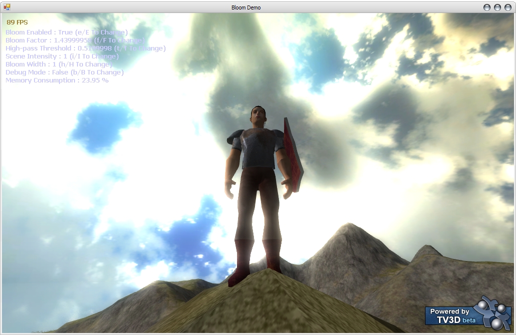
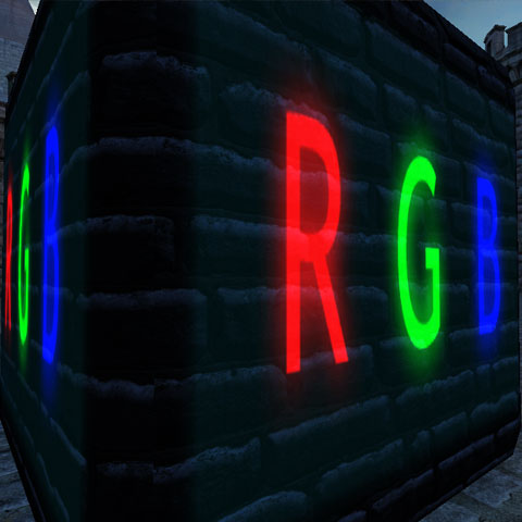
Another core part of God of War III‘s cinematic look and feel comes from the basic setup of the framebuffer, and the implementation of HDR lighting. Two framebuffer possibilities for HDR on the PlayStation 3 include LogLUV (aka NAO32, used in Uncharted and Heavenly Sword), and RGBM: an alternative setup that has found a home in Uncharted 2 and indeed in God of War III.

The basic technical setups for both formats are covered elsewhere but in terms of the final effect and what it means for the look of the game, the result is a massively expanded colour palette which gifts the artists with a higher-precision range of colours in which to create a unique, stylised and film-like look.

Opting for the RGBM setup over LogLUV means a significant saving in processing, although some precision is lost. The degree of that loss isn’t exactly apparent to the human eye, and we can assume it becomes even less of an issue bearing in mind that the final image is transmitted to your display downscaled over the 24-bit RGB link in the HDMI port.

Image

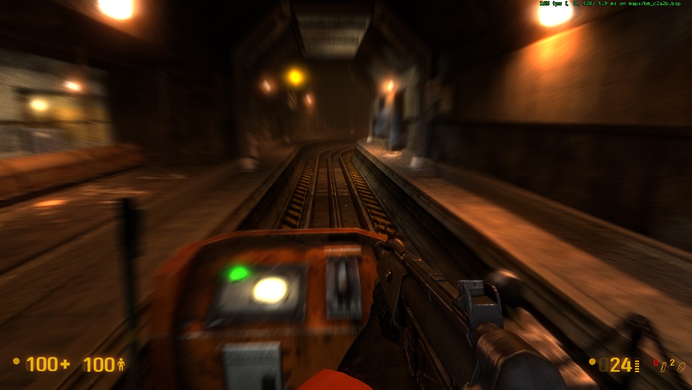
The filmic look of God of War III is boosted via effective motion blur. The shots demonstrate the camera and per-object implementations in the game.

In terms of post-processing effects, the game is given an additional boost in realism thanks to an impressive implementation of motion blur. Superficially, it’s a similar system to that seen in previous technological showcases like Uncharted 2: Among Thieves and Killzone 2, and helps to smooth some of the judder caused by a frame-rate that can vary between anything from 30 frames per second to 60.

Most games that implement motion blur do so just on a “camera” basis – that is, the whole scene is processed – an effect that of variable effectiveness in terms of achieving a realistic look.

According to Sony Santa Monica’s Ken Feldman, motion blur is calculated not just on the camera, but on an individual object and inner object basis too.

God of War’s camera and object motion blur is a subtle but effective contribution to the cinematic look of the game. Here at 30 per cent speed, the effect is more easily open to analysis. Hit the full-screen button for HD, or click on the EGTV link for a larger window.

The basics of the motion blur system effectively mimic what we see on the cinema screen. Movies run at only 24 frames per second, but make it look like it’s smoother. While filming, the shutter of the camera stays open for around 0.04 seconds. During that window of time, movement in the captured image is blurred. It’s that phenomenon that the tech seeks to mimic in God of War III: more cinematic, more realistic.

Initially the game used the RSX chip to carry out a traditional 2x multisampling anti-aliasing effect. This, combined with the game’s lack of high-contrast edges, produced an extremely clean look in last year’s E3 demo. For the final game, the Sony Santa Monica team implemented a solution that goes way beyond that.

MLAA-style edge-smoothing looks absolutely sensational in still shots but the effect often deteriorates with pixel-popping artifacts. In God of War III this only became especially obvious in the scene shown in the bottom right image.

According to director of technology Tim Moss, God of War III worked with the Sony technology group in the UK to produce an edge-smoothing technique for the game that the developers call MLAA, or morphological anti-aliasing. Indeed, Moss’s colleague Christer Ericson took us to task on the specifics of MLAA a few months back in this DF blog post, revealing that the team has put extensive research into this in search of their own solution.

“The core implementation of the anti-aliasing was written by some great SCEE guys in the UK, but came very late in our development cycle making the integration a daunting task,” adds senior staff programmer Ben Diamand.

The specifics of the implementation are still unknown at this time (though Ken Feldman suggests it “goes beyond” the papers Ericson spoke about in the DF piece) but the bottom line is that the final result in God of War III is simply phenomenal: aliasing is all but eliminated and the sub-pixel jitter typically associated with this technique has been massively reduced compared to other implementations we’ve seen. The implementation of MLAA culminates beautifully when it comes to eradicating edge-aliasing within the game.

The custom anti-aliasing solution is also another example of how PlayStation 3 developers are using the Cell CPU as a parallel graphics chip working in tandem with the RSX. The basic theory is all about moving tasks typically performed by the graphics chip over the Cell. Post-processing effects in particular work well being ported across.

The more flexible nature of the CPU means that while such tasks can be more computationally expensive, you are left with a higher-quality result. The increased latency incurred can be reduced by parallelising across multiple SPUs.

In the case of God of War III, frames take between 16ms and 30ms to render. The original 2x multisampling AA solution took a big chunk of rendering time, at 5ms. Now, the MLAA algorithm takes 20ms of CPU time. But it’s running across five SPUs, meaning that overall latency is a mere 4ms. So the final result is actually faster, and that previous 5ms of GPU time can be repurposed for other tasks.

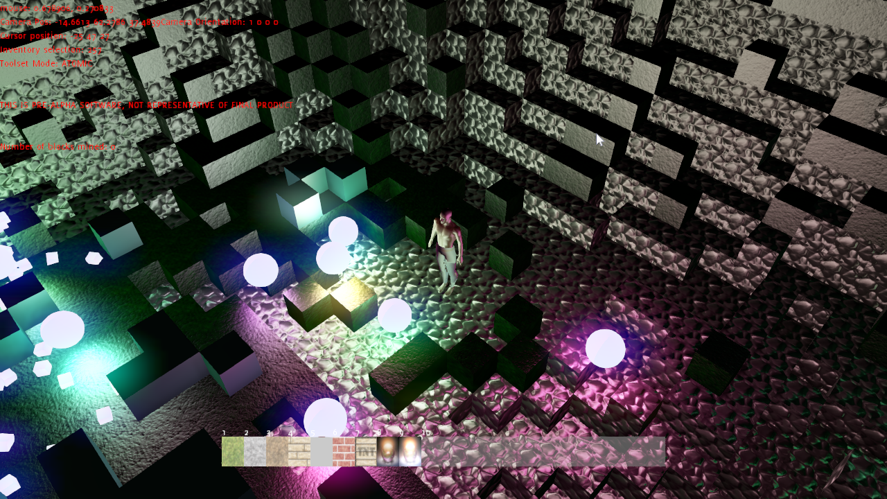
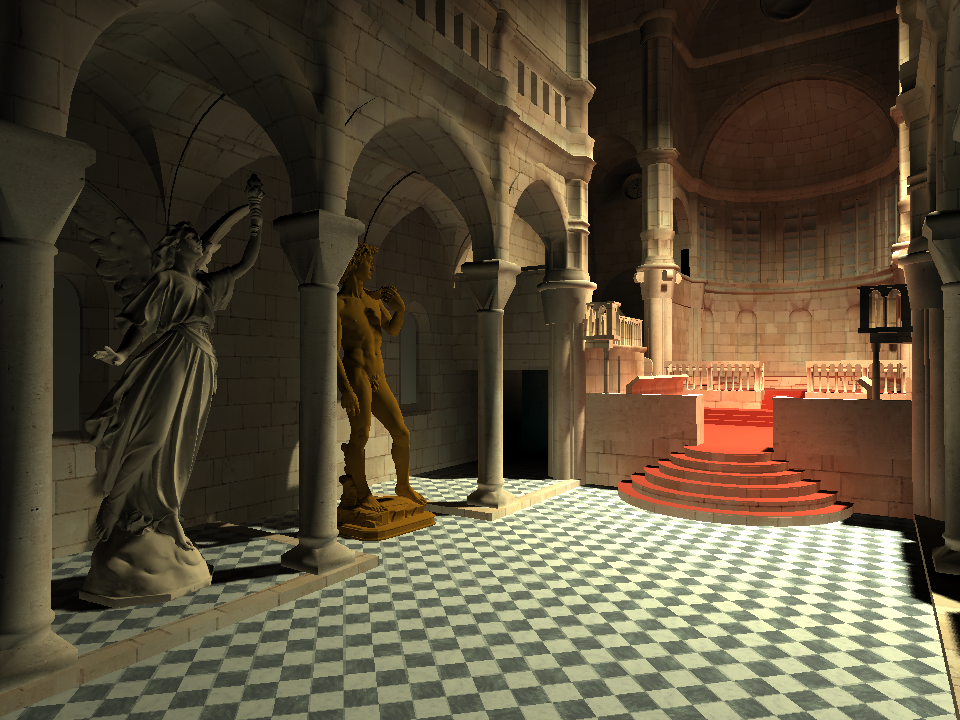
While the detail that the Sony Santa Monica team has put into the characters and environments is clearly immense, it’s the combination with the pure rendering tech that gives the game its state-of-the-art look and feel. The new God of War engine thrives in its handling of dynamic light sources, for example.

God of War III triumphs in handling dynamic lighting, with up to 50 lights per game object. Helios’ head (bottom right) is the most obvious example of the player directly interfacing with dynamic lighting. Dynamic lighting is one of the big features of the game’s engine. It manages to support up to 50 dynamic lights per game object. They are not using a deferred lighting scheme. Our lead programmer What the team did was place lights in Maya and have them update in real-time in the game on the PS3, it’s like being able to paint with lights.

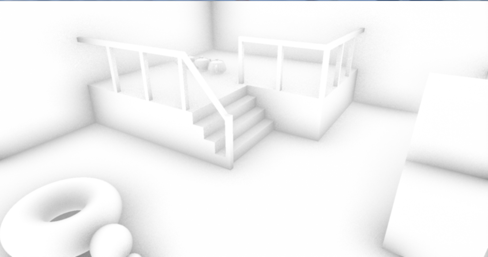
Where there is light, there is a shadow. Or at least there should be. On the majority of videogames, shadowing tech is fairly basic. Producing realistic shadows is computationally expensive, hence we get a range of ugly artifacts as a result: serrated edges that look ugly up close, or cascade shadow maps that transition in quality in stages right before your eyes.

Image

God of War III stands out in this regard simply because you don’t tend to notice the shadows. They’re realistic. The human eye is drawn to elements that stick out like a sore thumb, and that includes shadows. State-of-the-art techniques result in a very natural look. The result is subtle and it works beautifully, thus creating visual feast for players to enjoy as they play a game with graphics that even surpass blockbuster movies.

Shaders, the 3D photoshop Part 2

In my previous blogpost, I went over the many algorithms used in both 2D and 3D computer graphics. I talked about how they are essentially the same. We’ll use a screen shot from my game Under the Radar that I editted in photoshop, before and after respectively.

Image

Image

Drop shadowing in photoshop is the same as shadow mapping in which it checks if a point is visible from the light or not. If a point is visible from the light then it’s obviously not in shadow, otherwise it is. The basic shadow mapping algorithm can be described as short as this:

– Render the scene from the lights view and store the depths as shadow map

– Render the scene from the camera and compare the depths, if the current fragments depth is greater than the shadow depth then the fragment is in shadow

In some instances, drop shadows are used to make objects stand out of the background with a an outline, in shaders this is done with sobel edge filters.

The Sobel operator performs a 2-D spatial gradient measurement on an image and so emphasizes regions of high spatial frequency that correspond to edges. Typically it is used to find the approximate absolute gradient magnitude at each point in an input grayscale image.

In theory at least, the operator consists of a pair of 3×3 convolution kernels. One kernel is simply the other rotated by 90°. This is very similar to the Roberts Cross operator.

These kernels are designed to respond maximally to edges running vertically and horizontally relative to the pixel grid, one kernel for each of the two perpendicular orientations. The kernels can be applied separately to the input image, to produce separate measurements of the gradient component in each orientation (call these Gx and Gy). These can then be combined together to find the absolute magnitude of the gradient at each point and the orientation of that gradient.

In photoshop, filters are added to images to randomize the noise and alter the look. The equivalent in shaders is known as normal mapping. Normal maps are images that store the direction of normals directly in the RGB values of the image. They are much more accurate, as rather than only simulating the pixel being away from the face along a line, they can simulate that pixel being moved at any direction, in an arbitrary way. The drawbacks to normal maps are that unlike bump maps, which can easily be painted by hand, normal maps usually have to be generated in some way, often from higher resolution geometry than the geometry you’re applying the map to.

Normal maps in Blender store a normal as follows:

  • Red maps from (0-255) to X (-1.0 – 1.0)
  • Green maps from (0-255) to Y (-1.0 – 1.0)
  • Blue maps from (0-255) to Z (0.0 – 1.0)

Since normals all point towards a viewer, negative Z-values are not stored, also map blue colors (128-255) to (0.0 – 1.0). The latter convention is used in “Doom 3” as an example.

Those are a majority of effects that shaders use that are similar to photoshop effects, there’s also color adjustment which can be done in color to HSL shaders along with other sorts of effects.